753 Draw The Shear And Bendingmoment Diagrams For The Beam
753 Draw The Shear And Bendingmoment Diagrams For The Beam - ∑fy = 0 = −vr + p ⇒ vr = p. Web beam guru.com is a online calculator that generates bending moment diagrams (bmd) and shear force diagrams (sfd), axial force diagrams (afd) for any statically determinate (most simply supported and cantilever beams) and statically indeterminate beams, frames and trusses. In addition to the two principal values of bending moment at x = 0 m and at x = 5 m, the moments at other intermediate points should be determined to correctly draw the bending moment diagram. Then click on add segment button to add functions between the lines. Without there being any load applied to the beam, check that the beam is in its equilibrium position. Web statics last updated: Web you will be fully competent in drawing shear force and bending moment diagrams for statically determinate beams and frames. Web this problem has been solved! Divide the beam (of length l) into n segments. Web mechanical engineering questions and answers.
First, compute the reactions at the support. You will have a robust system of analysis that allows you to confidently tackle the analysis of. For the beam of figure 4: In this article, we’ll discuss bending moment diagrams in detail and how to construct them. The bending moment diagram of the. Neglect the mass of the beam in each problem. Click on add discontinuity to add discontinuity lines. Divide the beam (of length l) into n segments. Click on add discontinuity to add discontinuity lines. Web this problem has been solved!
Shear force and bending moment diagrams are powerful graphical methods that are used to analyze a beam under loading. View the full answer step 2. Web you will be fully competent in drawing shear force and bending moment diagrams for statically determinate beams and frames. Draw the shear diagram for the beam. Web mechanical engineering questions and answers. 3 3 9 kn/m 9 kn/m. Web royal melbourne institute of technology. Web you'll get a detailed solution from a subject matter expert that helps you learn core concepts. Students have asked these similar. Assume that the flexural rigidity is a multiple of ei and differs for each member as shown in the figure.

Beam shear and bending moment diagrams sekajava
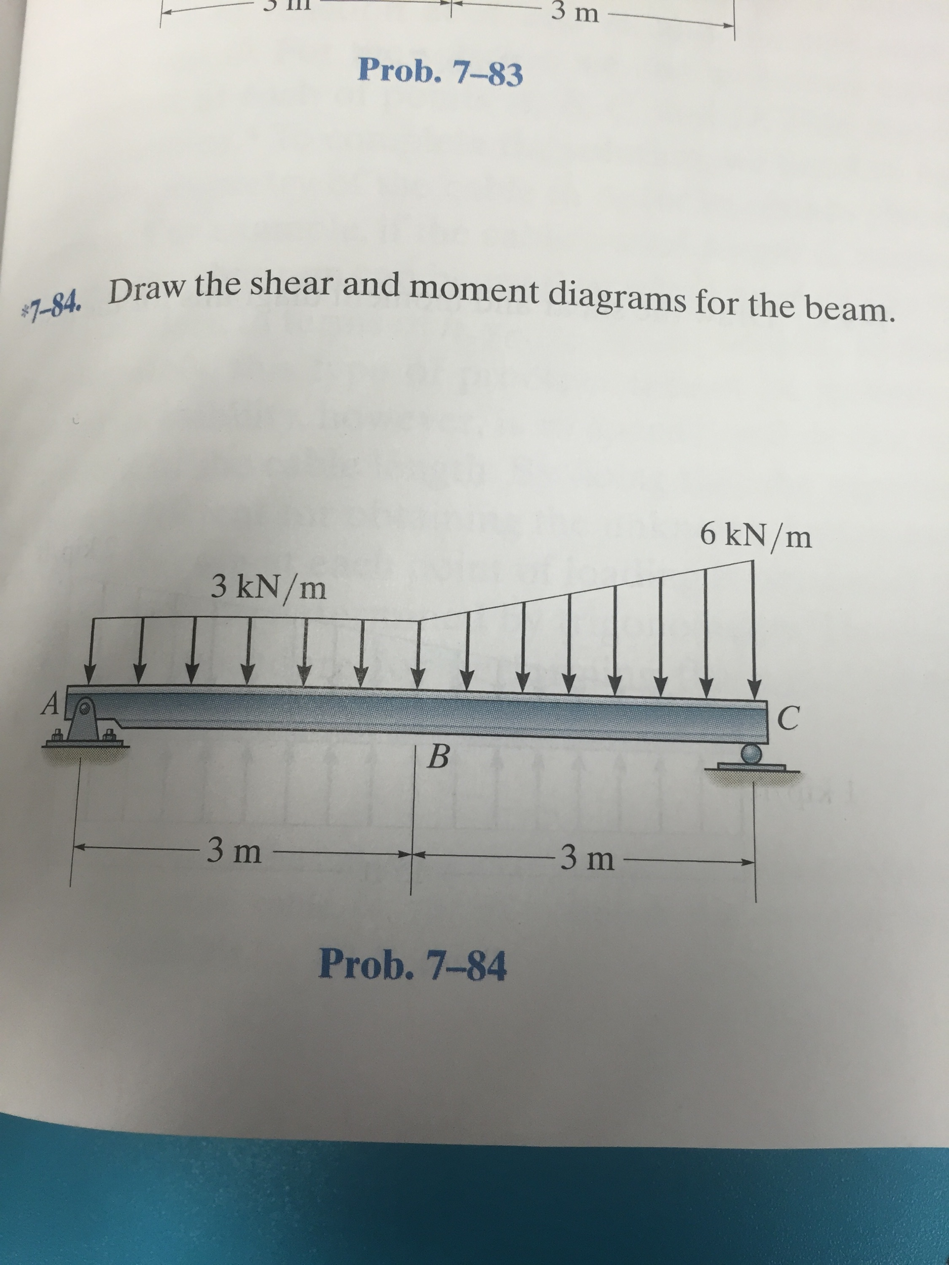
Web shear and moment diagrams are graphs which show the internal shear and bending moment plotted along the length of the beam. Draw the shear and moment diagrams for the beam. Students have asked these similar. Description of the device 1 is the beam 2 is the load hanger 3 is the shear force load hanger 4 is the bending.

Shear Force and Bending Moment diagram of Beam with Triangular Load
There are 4 steps to solve this one. Write shear and moment equations for the beams in the following problems. Neglect the mass of the beam in each problem. You'll get a detailed solution from a subject matter expert that helps you learn core concepts. Draw the shear and moment diagrams for the beam.

Shear and moment diagrams geekloki
Web ay this will allow you to find external ex bx' bx' bx bx by' by' by by cy ey reaction forces at the supports and internal reaction forces at the hinge. Web since the function for the bending moment is parabolic, the bending moment diagram is a curve. Problem 7.53 draw the shear diagram for the beam. Draw the.

Shear force & Bending moment diagram for Overhanging Beam YouTube
∑fy = 0 = −vr + p ⇒ vr = p. 3 3 9 kn/m 9 kn/m. In addition to the two principal values of bending moment at x = 0 m and at x = 5 m, the moments at other intermediate points should be determined to correctly draw the bending moment diagram. You'll get a detailed solution from.
Solved Draw the shear and moment diagrams for the beam.
Web royal melbourne institute of technology. View the full answer step 2. Shear force and bending moment diagrams are powerful graphical methods that are used to analyze a beam under loading. Assume that the flexural rigidity is a multiple of ei and differs for each member as shown in the figure. In this article, we’ll discuss bending moment diagrams in.

Learn How To Draw Shear Force And Bending Moment Diagrams Engineering
Web beam guru.com is a online calculator that generates bending moment diagrams (bmd) and shear force diagrams (sfd), axial force diagrams (afd) for any statically determinate (most simply supported and cantilever beams) and statically indeterminate beams, frames and trusses. Adjust the tension springs if necessary. 172k views 5 years ago civil engineering/structural engineering. The beginning, end, or change of a.

Learn How To Draw Shear Force And Bending Moment Diagrams Engineering
In this article, we’ll discuss bending moment diagrams in detail and how to construct them. Finally calculating the moments can be done in the following. Draw the shear diagram for the beam. Write answers in the space provided. For the beam of figure 4:

Draw the shear and moment diagrams for the beam.
Skyciv beam tool guides users along a professional beam calculation workflow, culminating in the ability to view and determine if they comply with your region's design codes. Draw the shear and moment diagrams for the beam 9k n/m 9 kn/m in 3 m. 172k views 5 years ago civil engineering/structural engineering. The bending moment diagram of the. Web statics last.
Beam shear and bending moment diagrams Olfedubai
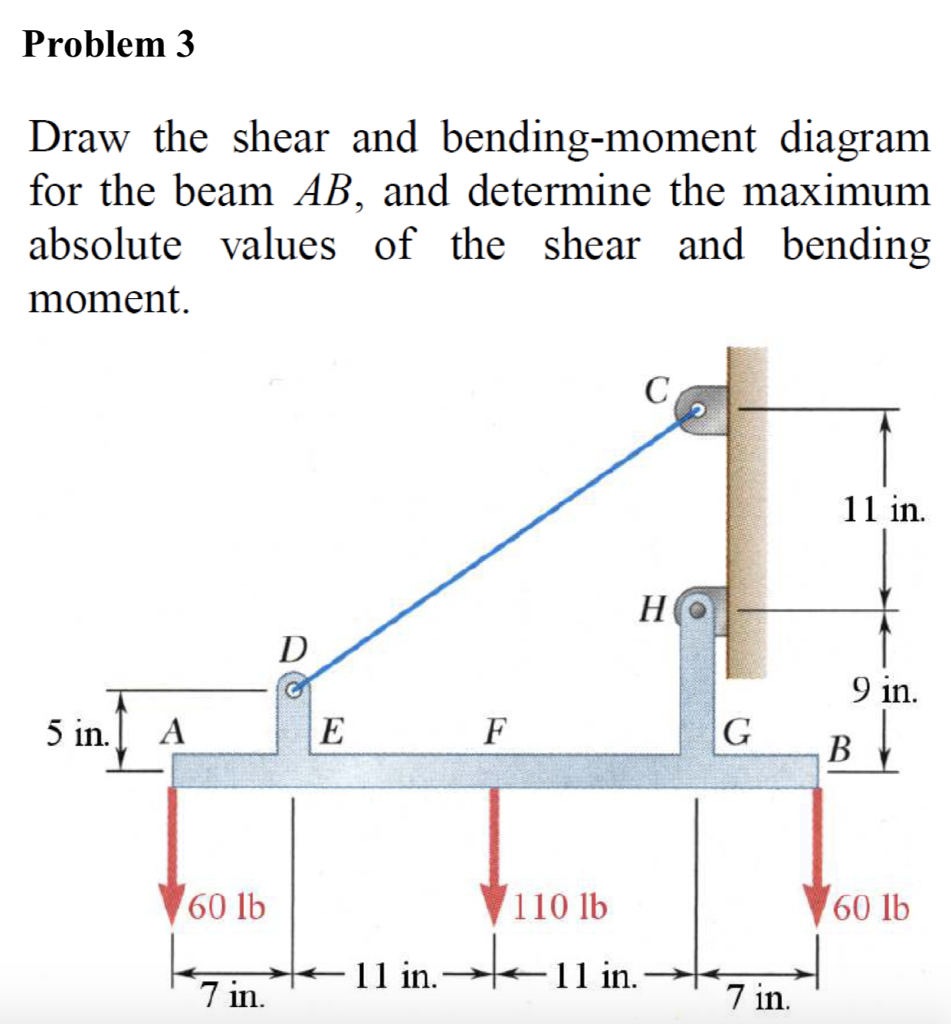
Finally calculating the moments can be done in the following. View the full answer step 2. Once you have the reactions, draw your free body diagram and shear force diagram underneath the beam. Write shear and moment equations for the beams in the following problems. Also, draw shear and moment diagrams, specifying values at all change of loading positions and.

Learn How To Draw Shear Force And Bending Moment Diagrams Engineering
You'll get a detailed solution from a subject matter expert that helps you learn core concepts. Web beam guru.com is a online calculator that generates bending moment diagrams (bmd) and shear force diagrams (sfd), axial force diagrams (afd) for any statically determinate (most simply supported and cantilever beams) and statically indeterminate beams, frames and trusses. Skyciv beam tool guides users.
They Allow Us To See Where The Maximum Loads Occur So That We Can Optimize The Design To Prevent Failures And Reduce The Overall Weight And Cost Of The Structure.
Web in order to construct shear and moment diagrams for a beam, first, determine the reactive forces and couple moments acting on the beam, and resolve all the forces into components acting perpendicular and parallel to the beam’s axis. You'll get a detailed solution from a subject matter expert that helps you learn core concepts. Skyciv beam tool guides users along a professional beam calculation workflow, culminating in the ability to view and determine if they comply with your region's design codes. Assume that the flexural rigidity is a multiple of ei and differs for each member as shown in the figure.
Web Mechanical Engineering Questions And Answers.
Web shear force and bending moment diagrams are analytical tools used in conjunction with structural analysis to help perform structural design by determining the value of shear forces and bending moments at a given point of a structural element such as a beam. The bending moment diagram of the. V(x) = vr = p = constant. Neglect the mass of the beam in each problem.
In Addition To The Two Principal Values Of Bending Moment At X = 0 M And At X = 5 M, The Moments At Other Intermediate Points Should Be Determined To Correctly Draw The Bending Moment Diagram.
Write answers in the space provided. This problem has been solved! Web royal melbourne institute of technology. You will have a robust system of analysis that allows you to confidently tackle the analysis of.
∑Fy = 0 = −Vr + P ⇒ Vr = P.
Web ay this will allow you to find external ex bx' bx' bx bx by' by' by by cy ey reaction forces at the supports and internal reaction forces at the hinge. Web beam guru.com is a online calculator that generates bending moment diagrams (bmd) and shear force diagrams (sfd), axial force diagrams (afd) for any statically determinate (most simply supported and cantilever beams) and statically indeterminate beams, frames and trusses. Mmax = 84 knm, σmax = 98.9 mpa. In each problem, let x be the distance measured from left end of the beam.