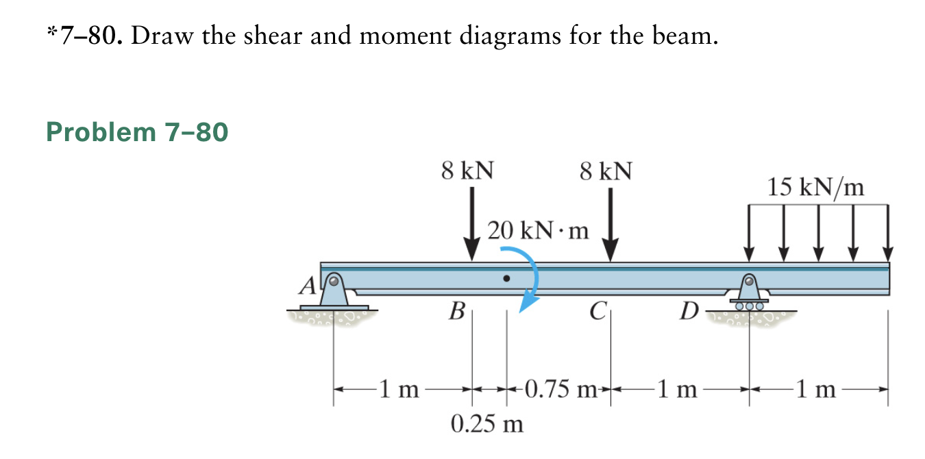
780 Draw The Shear And Moment Diagrams For The Beam
780 Draw The Shear And Moment Diagrams For The Beam - Assume that the flexural rigidity is a multiple of ei and differs for each member as shown in the figure. Determine all the reactions on the beam. A strut column would be an element design. Civil engineering questions and answers. F 1 = 800n f 2 = 600n m = 1200n⋅m. 30 kn/m 60 kn d 2m fig.p5.9 1m 2m. 480 views 4 months ago chapter 6 (bending) by mechanics of materials r.c hibbeler (9th edition), complete solution by engr adnan rasheed mechanical. You'll get a detailed solution from a subject matter expert that helps you learn core concepts. 80% (5 ratings) share share. Web the first step in calculating these quantities and their spatial variation consists of constructing shear and bending moment diagrams, \(v(x)\) and \(m(x)\), which are the internal shearing forces and bending moments induced in.
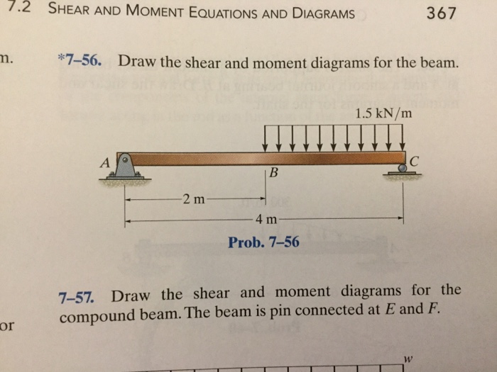
There’s just one step to solve this. Web this is an example problem that will show you how to graphically draw a shear and moment diagram for a beam. Web our calculator generates the reactions, shear force diagrams (sfd), bending moment diagrams (bmd), deflection, and stress of a cantilever beam or simply supported beam. Write shear and moment equations for the beams in the following problems. 7.3k views 2 years ago statics. Web draw the shear and moment diagrams for the beam. Draw shear diagram (identify all important shear values, slopes, and convention on the diagram) c. Assume that the flexural rigidity is a multiple of ei and differs for each member as shown in the figure. Part a draw the shear diagram for the beam. You'll get a detailed solution from a subject matter expert that helps you learn core concepts.
You will have a robust system of analysis that allows you to confidently tackle the analysis of. (a) 72.0 kn, (b) 96.0 knm. 7.3k views 2 years ago statics. There’s just one step to solve this. Civil engineering questions and answers. The forces and moment acting on the beam are: Assume that the flexural rigidity is a multiple of ei and differs for each member as shown in the figure. Neglect the mass of the beam in each problem. 80% (5 ratings) share share. Web shear and moment diagrams are graphs which show the internal shear and bending moment plotted along the length of the beam.
Solved *780. Draw the shear and moment diagrams for the
30 kn/m 60 kn d 2m fig.p5.9 1m 2m. Web you will be fully competent in drawing shear force and bending moment diagrams for statically determinate beams and frames. You'll get a detailed solution from a subject matter expert that helps you learn core concepts. A strut column would be an element design. In general the process goes like this:
draw the shear and moment diagrams for the beam chegg
The beginning, end, or change of a load pattern. Civil engineering questions and answers. You'll get a detailed solution from a subject matter expert that helps you learn core concepts. 1) calculate support reactions 2). Part b draw the moment diagram for the beam.
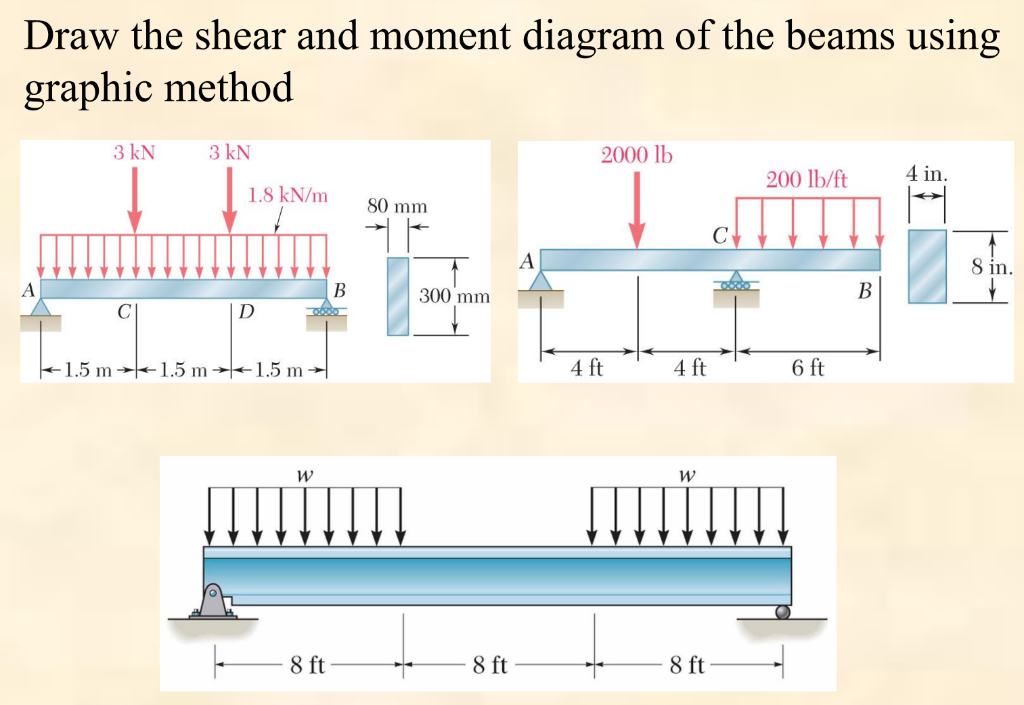
Solved Draw the shear and moment diagram of the beams using
There are 2 steps to solve this one. 480 views 4 months ago chapter 6 (bending) by mechanics of materials r.c hibbeler (9th edition), complete solution by engr adnan rasheed mechanical. Draw the shear and moment diagrams for the beam.problem from engineering mechanics statics, fifteenth edition. Internal forces in beams and frames, libretexts. Civil engineering questions and answers.
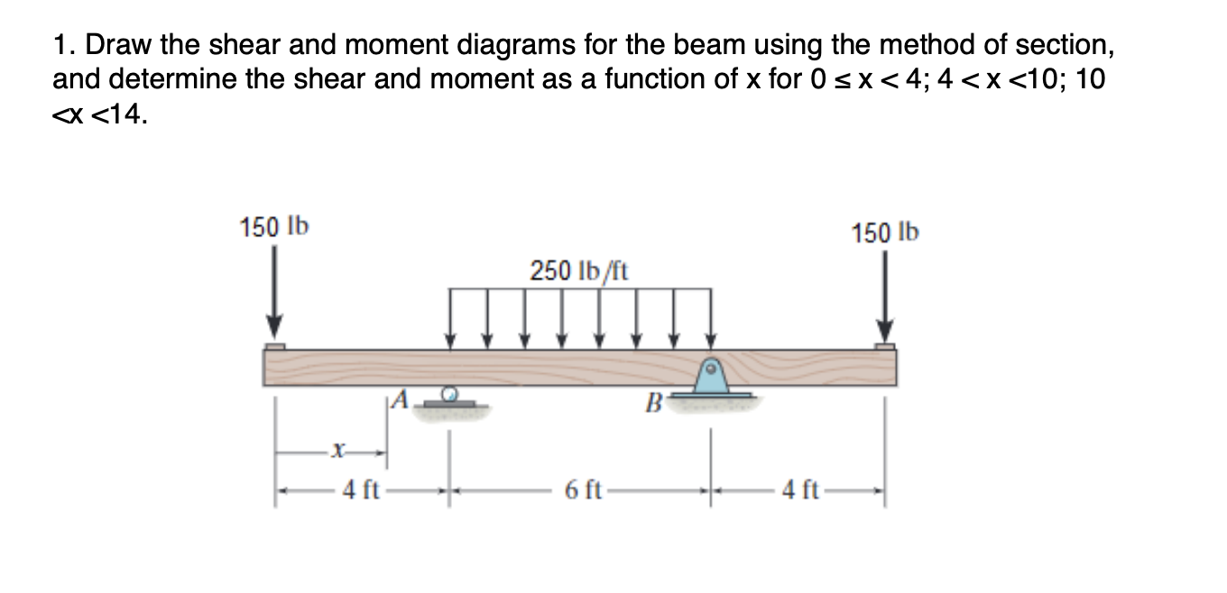
Solved 1. Draw the shear and moment diagrams for the beam
Web learning by teaching. The forces and moment acting on the beam are: 11k views 2 years ago statics. Once these are determined, derive the shear and moment functions. Write answers in the space provided.
draw the shear and moment diagrams for the beam chegg
Shear and bending moment equations. You'll get a detailed solution from a subject matter expert that helps you learn core concepts. There’s just one step to solve this. Web learn to draw shear force and moment diagrams using 2 methods, step by step. Write shear and moment equations for the beams in the following problems.

Draw the shear and moment diagrams for the beam.
We are required to draw the shear force and bending moment diagram for the given beam. 1) calculate support reactions 2). We go through breaking a beam into segments, and then we learn about the relationships between shear force. 30 kn/m 60 kn d 2m fig.p5.9 1m 2m. Web our calculator generates the reactions, shear force diagrams (sfd), bending moment.

Learn How To Draw Shear Force And Bending Moment Diagrams Engineering
100% (10 ratings) share share. 11k views 2 years ago statics. Once these are determined, derive the shear and moment functions. Web our calculator generates the reactions, shear force diagrams (sfd), bending moment diagrams (bmd), deflection, and stress of a cantilever beam or simply supported beam. We go through breaking a beam into segments, and then we learn about the.

Shear and moment diagrams geekloki
Ft а в 4 ft 2 ft 3 ft prob. Web civil engineering questions and answers. Web below is a simple example of what shear and moment diagrams look like, afterwards, the relation between the load on the beam and the diagrams will be discussed. Part b draw the moment diagram for the beam. Skyciv beam tool guides users along.

Shear And Moment Diagrams For Beams
Neglect the mass of the beam in each problem. Web in order to construct shear and moment diagrams for a beam, first, determine the reactive forces and couple moments acting on the beam, and resolve all the forces into components acting perpendicular and parallel to the beam’s axis. In general the process goes like this: Draw the shear and moment.

Shear And Moment Diagrams For Beams
You'll get a detailed solution from a subject matter expert that helps you learn core concepts. Web our calculator generates the reactions, shear force diagrams (sfd), bending moment diagrams (bmd), deflection, and stress of a cantilever beam or simply supported beam. We are required to draw the shear force and bending moment diagram for the given beam. Neglect the mass.
Draw Shear Diagram (Identify All Important Shear Values, Slopes, And Convention On The Diagram) C.
In general the process goes like this: Also, draw shear and moment diagrams, specifying values at all change of loading positions and at points of zero shear. Web shear and moment diagrams are graphs which show the internal shear and bending moment plotted along the length of the beam. 11k views 2 years ago statics.
The Beginning, End, Or Change Of A Load Pattern.
Web figures 1 through 32 provide a series of shear and moment diagrams with accompanying formulas for design of beams under various static loading conditions. Web learn to draw shear force and moment diagrams using 2 methods, step by step. Draw the shear and moment diagrams for the beam.problem from engineering mechanics statics, fifteenth edition. Web the first step in calculating these quantities and their spatial variation consists of constructing shear and bending moment diagrams, \(v(x)\) and \(m(x)\), which are the internal shearing forces and bending moments induced in.
They Allow Us To See Where The Maximum Loads Occur So That We Can Optimize The Design To Prevent Failures And Reduce The Overall Weight And Cost Of The Structure.
You will have a robust system of analysis that allows you to confidently tackle the analysis of. Draw the shear and moment diagrams for the beam. 100% (10 ratings) share share. There are 2 steps to solve this one.
Neglect The Mass Of The Beam In Each Problem.
7.3k views 2 years ago statics. This problem has been solved! Draw the moment diagram (identify all important moment values, slopes. In each problem, let x be the distance measured from left end of the beam.