Architectural Drawing Dimensions
Architectural Drawing Dimensions - 8.3 x 11.7” (210 x 297mm) a5: What this means is the face of a concrete column can be an inch in either direction from where you think it should be. 16.5 x 23.4” (420 x 594mm) a3: Web ansi standard us engineering drawing sizes: A comprehensive reference database of dimensioned drawings documenting the standard measurements and sizes of the everyday objects and spaces that make up our world. 36 x 48” (914 x 1219mm) In architectural and structural sketches and drawings, the numerals are usually above an unbroken dimension line. Mep (mechanical, electrical, and plumbing) a. Web architect bryan maddock created a public research database dubbed dimensions.guide as a comprehensive reference for dimensioned drawings. 9 x 12” (229 x 305mm) arch b:
Web standard us architectural drawing sizes. Web architects dimensions & drawings | dimensions.com. 9 x 12” (229 x 305mm) arch b: In architectural and structural sketches and drawings, the numerals are usually above an unbroken dimension line. Identify the key features of the object that need to be dimensioned, such as walls, windows, doors, or other elements. Web all architecture drawings are drawn to a scale and as described here in great detail, there are set scales that should be used depending on which drawing is being produced, some of which are below: Dimensioning columns even to half an inch is probably asking for unachievable precision. Web for reference, every set of architectural drawings includes a symbol legend. A plan drawing shows a view from above. 5.8 x 8.3” (148 x 210mm) arch paper sizes.
And build on their ideas when you materialize your own project. Web standard us architectural drawing sizes. This is the way that all imperial measurements are. Web ansi standard us engineering drawing sizes: Web architects dimensions & drawings | dimensions.com. 23.4 x 33.1” (594 x 841mm) a2: Mep (mechanical, electrical, and plumbing) a. Web in machine sketches and drawings, in which fractions and decimals are used for dimensions, the dimension line is usually broken near the middle to provide open space for the dimension numerals. 12 x 18” (305 x 457mm) arch c: 5.8 x 8.3” (148 x 210mm) arch paper sizes.
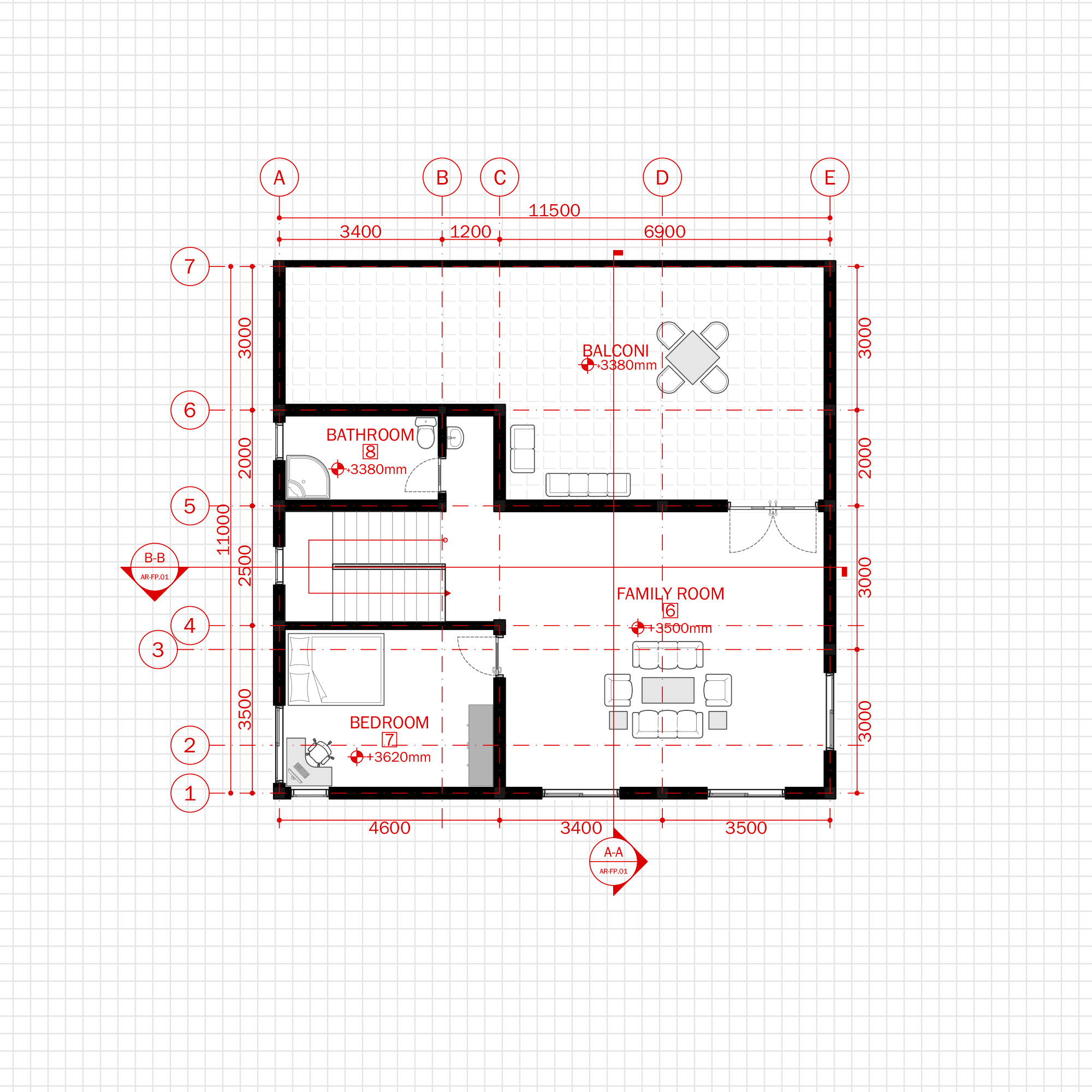
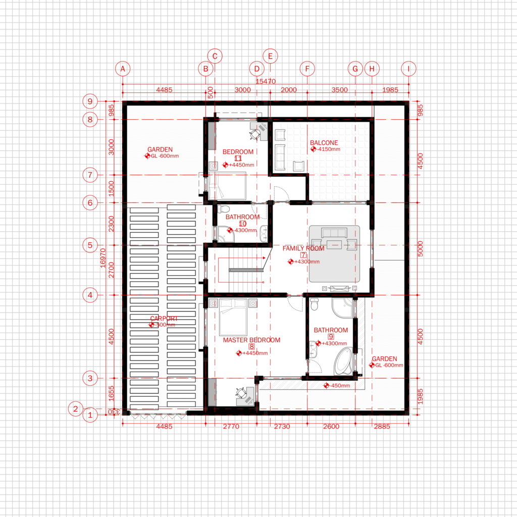
Simple Modern House 1 Architecture Plan with floor plan, metric units
Architecture drawings are important for several reasons: Floor plan notes give additional context for the building. If you aren’t familiar with a symbol, you will be able to find it in the legend. 11.7 x 16.5” (297 x 420mm) a4: Web standard us architectural drawing sizes.

Architectural Graphic Standards Life of an Architect How to plan
Documenting the standard measurements and sizes. Web all architecture drawings are drawn to a scale and as described here in great detail, there are set scales that should be used depending on which drawing is being produced, some of which are below: Floor plan notes give additional context for the building. A comprehensive reference database of dimensioned drawings documenting the.
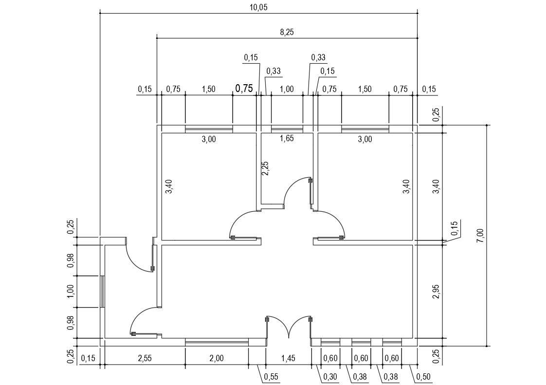
Architectural floor plan Drawing with dimension is available in this
This is often used to depict the layout of a building, showing locations of. Web for reference, every set of architectural drawings includes a symbol legend. Start by drawing the architectural plan or elevation of the object you want to dimension using a drafting software or a pencil and paper. 23.4 x 33.1” (594 x 841mm) a2: If you aren’t.
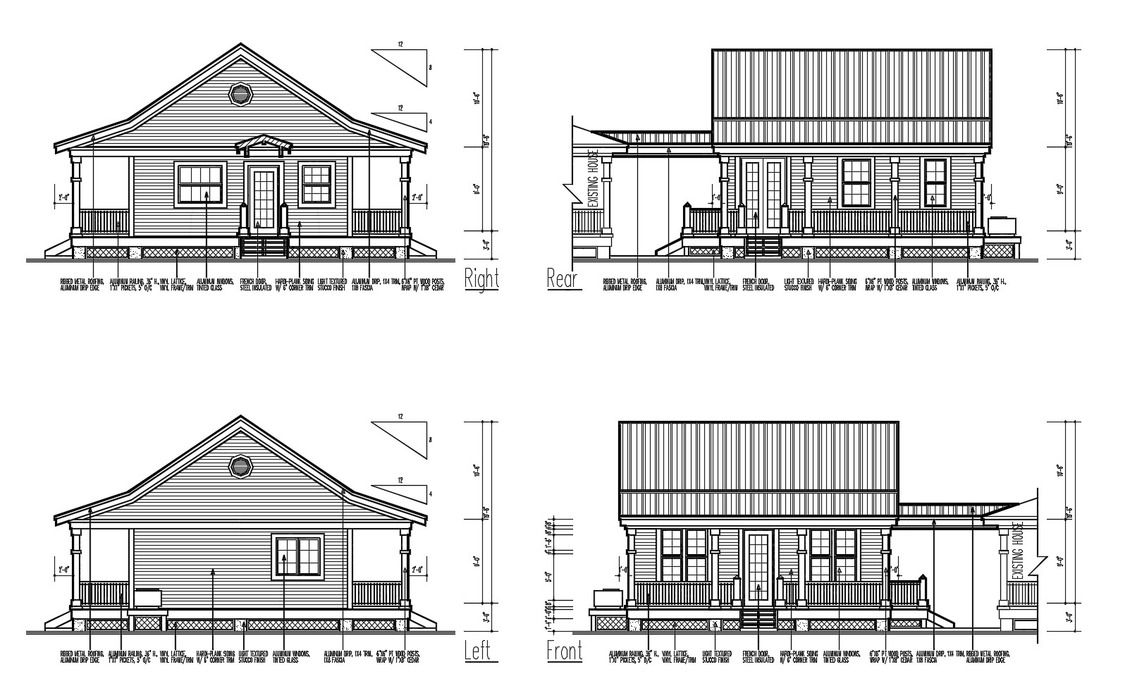
Elevation drawing of a house design with detail dimension in AutoCAD
Dwg (ft) dwg (m) svg. Web an architectural drawing is a sketch, plan, diagram, or schematic that communicates detailed information about a building. Architectural scale, a fundamental concept in the design and perception of buildings and spaces, serves as an essential bridge between abstract ideas and tangible realities. Web scaled 2d drawings and 3d models available for download. Web just.
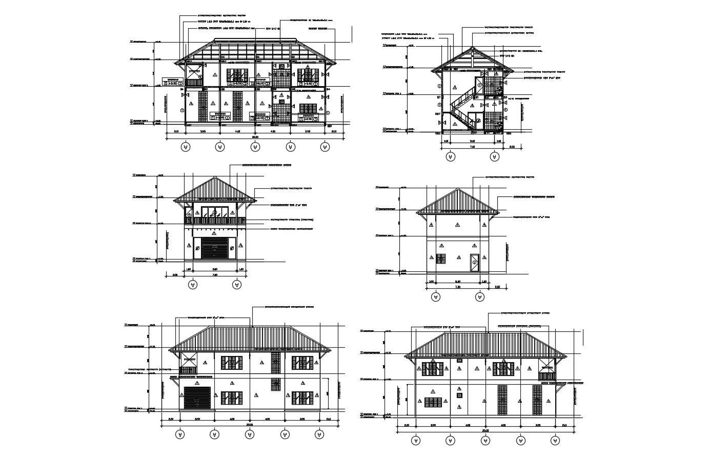
Elevation drawing of a house with detail dimension in dwg file Cadbull
12 x 18” (305 x 457mm) arch c: What this means is the face of a concrete column can be an inch in either direction from where you think it should be. Dwg (ft) dwg (m) svg. Dwg (ft) dwg (m) svg. They typically include dimensions, materials, construction methods, and other important information necessary for construction.
Residential Modern House Architecture Plan with floor plan metric units
For instance, the notes can clarify exactly to what point on a wall dimensions should be measured. Web just adding dimensions in a drawing is not always sufficient and if you want the machinist, architect or stakeholders to read your drawing exactly the same way every time then you should follow the dimensioning best practices as outlined in this article..

Structural Drawing For Residential Building A Comprehensive Guide
12 x 18” (305 x 457mm) arch c: Gypsum board partitions in plan: This is often used to depict the layout of a building, showing locations of. In architectural and structural sketches and drawings, the numerals are usually above an unbroken dimension line. Web in machine sketches and drawings, in which fractions and decimals are used for dimensions, the dimension.
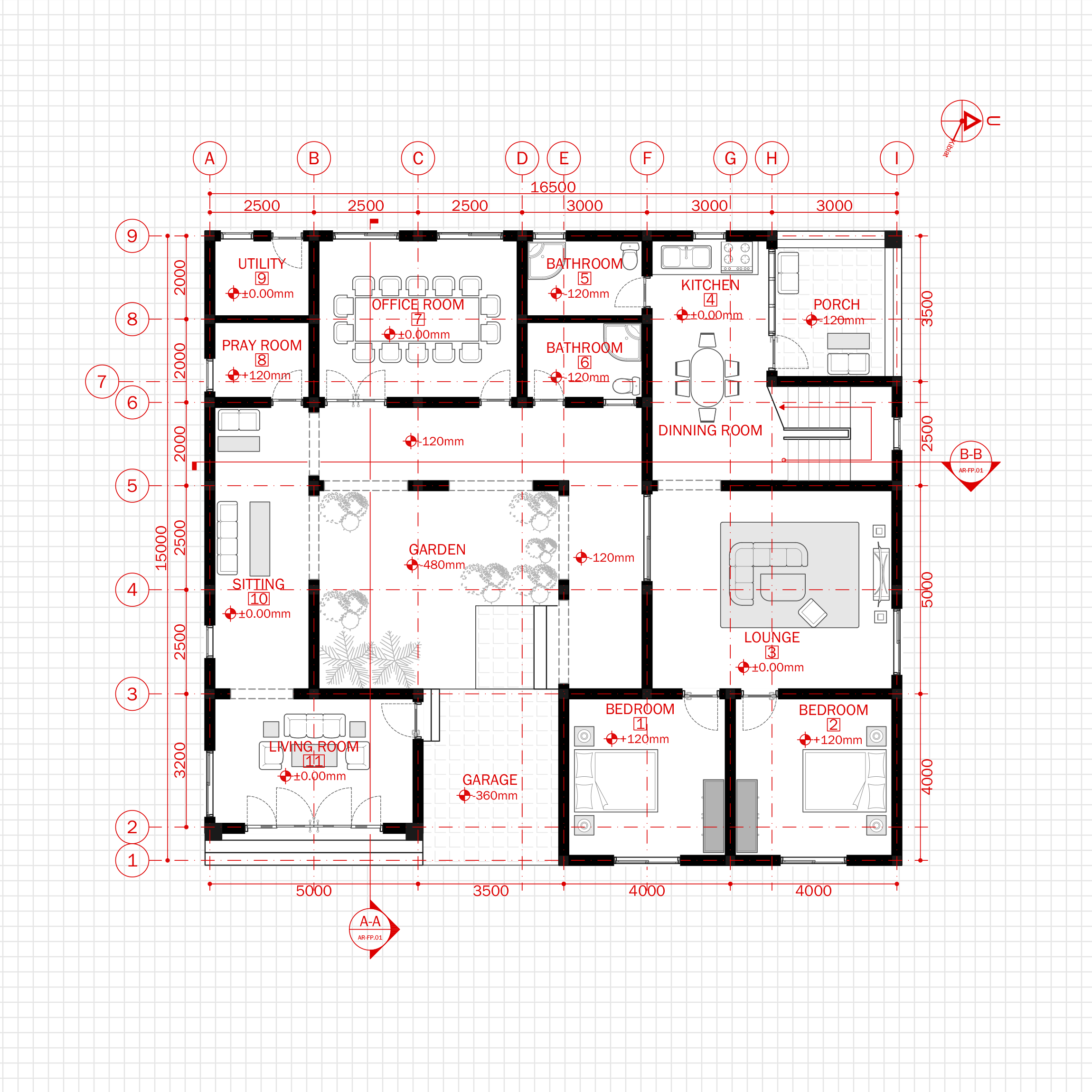
Modern House Office Architecture Plan with floor plan metric units
This is often used to depict the layout of a building, showing locations of. Web architectural drawings are made according to a set of conventions, which include particular views (floor plan, section etc.), sheet sizes, units of measurement and scales, annotation and cross referencing. Reflected ceiling plan or rcp. Web learn from other architects how they designed their plans, sections.

Architectural House Building Design With Dimension DWG Drawing
A comprehensive reference database of dimensioned drawings documenting the standard measurements and sizes of the everyday objects and spaces that make up our world. Dwg (ft) dwg (m) svg. Identify the key features of the object that need to be dimensioned, such as walls, windows, doors, or other elements. In architectural and structural sketches and drawings, the numerals are usually.

Typical Architectural Drawing Sizes The Architect
5.8 x 8.3” (148 x 210mm) arch paper sizes. 18 x 24” (457 x 610mm) arch d: 24 x 36” (610 x 914mm) arch e: Web all architecture drawings are drawn to a scale and as described here in great detail, there are set scales that should be used depending on which drawing is being produced, some of which are.
If You Aren’t Familiar With A Symbol, You Will Be Able To Find It In The Legend.
Architecture drawings are important for several reasons: Dwg (ft) dwg (m) svg. Web architectural blueprints are technical drawings that represent the design and details of a building project. Web in machine sketches and drawings, in which fractions and decimals are used for dimensions, the dimension line is usually broken near the middle to provide open space for the dimension numerals.
They Typically Include Dimensions, Materials, Construction Methods, And Other Important Information Necessary For Construction.
Dwg (ft) dwg (m) svg. What this means is the face of a concrete column can be an inch in either direction from where you think it should be. 16.5 x 23.4” (420 x 594mm) a3: Web here are the standard us architectural drawing sizes:
Web The Purpose Of A Floor Plan Is Show A Dimensioned And Scaled Map Of A Building’s Interior Spaces, Depicting The Relationship To One Another, Connections Between The Interior And Exterior, And The Location Of Key Elements Such As Openings, Objects And Wall Thickness’s.
This is the way that all imperial measurements are. 36 x 48” (914 x 1219mm) Dwg (ft) dwg (m) svg. 9 x 12” (229 x 305mm) arch b:
Web Just Adding Dimensions In A Drawing Is Not Always Sufficient And If You Want The Machinist, Architect Or Stakeholders To Read Your Drawing Exactly The Same Way Every Time Then You Should Follow The Dimensioning Best Practices As Outlined In This Article.
Start by drawing the architectural plan or elevation of the object you want to dimension using a drafting software or a pencil and paper. 18 x 24” (457 x 610mm) arch d: 12 x 18” (305 x 457mm) arch c: Architects and designers create these types of technical drawings during the planning stages of a construction project.