Auxiliary View Engineering Drawing
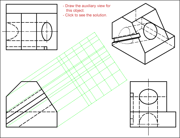
Auxiliary View Engineering Drawing - Web auxiliary view in engineering drawing is a special type of orthographic projection that provides additional information about the object being represented. Web draw primary auxiliary views representing the true shapes of surfaces that are perpendicular to one of the reference planes and inclined to the other two. Since the top view of the line appears inclined to vp at 600, draw the x 2y 2 line inclined at 600 to the auxiliary top. Web auxiliary views are commonly found on many types of industrial drawings. Construct depth, height, or width auxiliary views. Web there are three basic type of auxiliary views. Web to project an auxiliary top view on aip, draw projections from a 1’ and b 1’ perpendicular to x 1y 1 line, and on them step off 1a 1=3a and 2b 1=4b from the x 1y 1 line. Auxiliary views are used when showing true dimensions of parts that are on an inclined angle. There are three basic type of auxiliary views. Method of preparation of auxiliary views.
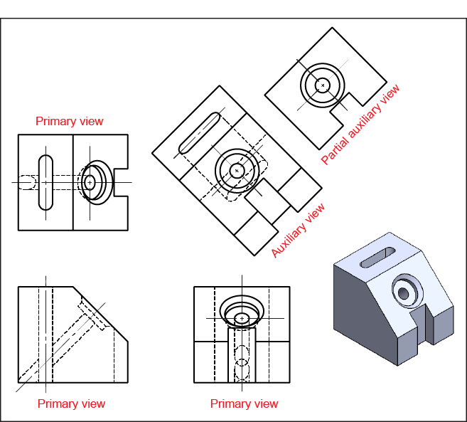
Connect ab which will be the auxiliary top view. Plot curves in auxiliary views. Draw apparent shapes of surfaces in either the principal views or auxiliary views, if at least one of the views represents the true shape. Web we will now discuss various types of engineering drawings or cad drawing views including: Object so that the true size and shape of the surf ace (or surfaces) are seen as they actually are. It is created from at least two principal views with the aim of showing the true shape and size of a feature. Practice tests for auxiliary views engineering drawing. Web auxiliary views are commonly found on many types of industrial drawings. Create an auxiliary view from orthographic views. Ideally, the view that is created should be shown in line with the direction of view.
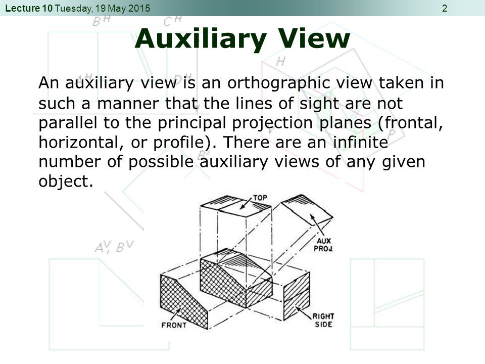
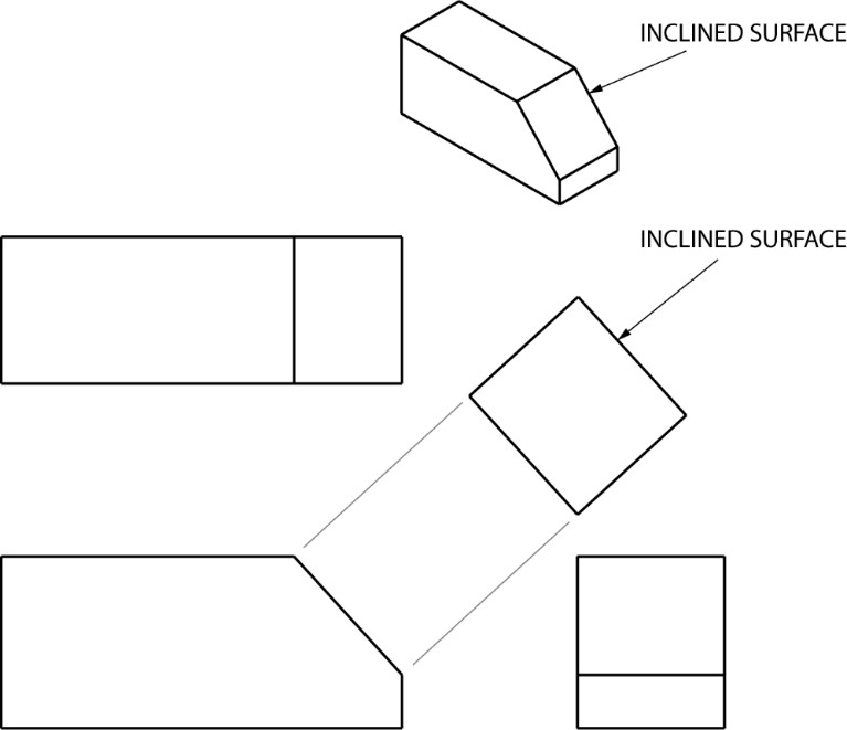
An auxiliary view is an orthographic view on a plane that is not one of the principal planes of projection. It turns, or projects, the. Web auxiliary views are commonly found on many types of industrial drawings. An isometric view of a rectangular block is shown in fig. Method of preparation of auxiliary views. There are three basic type of auxiliary views. Web to project an auxiliary top view on aip, draw projections from a 1’ and b 1’ perpendicular to x 1y 1 line, and on them step off 1a 1=3a and 2b 1=4b from the x 1y 1 line. Object so that the true size and shape of the surf ace (or surfaces) are seen as they actually are. You will need your textbook worksheet for this exercise. Web an auxiliary view is simply a “helper” view, which shows the slanted part of the object as it actually is.
Introduction to Engineering Drawings
In the first type, the auxiliary view is projected from the front view of a three view (orthographic) drawing. Since the top view of the line appears inclined to vp at 600, draw the x 2y 2 line inclined at 600 to the auxiliary top. Orthographic projection, axonometric projection, sectional views, auxiliary views, detailed views, broken views and exploded view..
Auxiliary Views FREEMAN'S TECH ED SITE
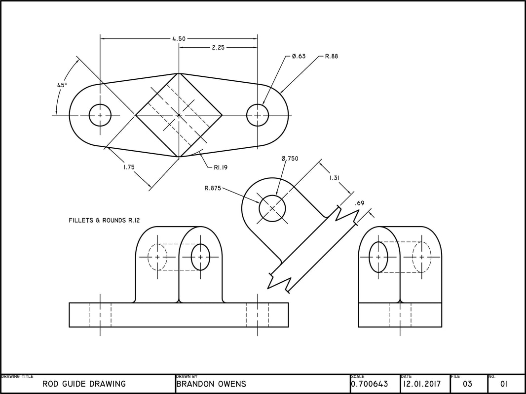
Web section views and auxiliary views are two types of projections that help engineers and designers communicate the shape and details of complex objects on engineering drawings. Create an auxiliary view from orthographic views. When creating engineering drawings, it is often neccessary to show features in a view where they appear true size so that they can be dimensioned. The.
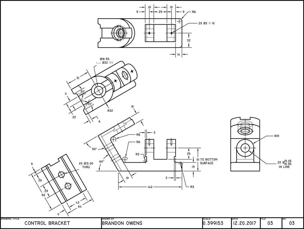
AUXILIARY DRAWINGS BRANDON OWENS' PORTFOLIO
Auxiliary views are commonly found on many types of industrial drawings. Construct depth, height, or width auxiliary views. When creating engineering drawings, it is often neccessary to show features in a view where they appear true size so that they can be dimensioned. Ideally, the view that is created should be shown in line with the direction of view. National.

Drawing 04_01 Primary Auxiliary View YouTube
You can think of an auxiliary view as a specialty view that is sometimes necessary for design clarity or dimensioning purposes for a. Web to project an auxiliary top view on aip, draw projections from a 1’ and b 1’ perpendicular to x 1y 1 line, and on them step off 1a 1=3a and 2b 1=4b from the x 1y.
What Is Auxiliary Plane Types of Auxiliary Plane Types of Auxiliary
The horizontal lines (parallel lines) are drawn with a 30° angle to the horizontal axis and the vertical line of the parts are normal to the vertical axis or perpendicular to the horizontal axis. This exercise takes you through the steps required to construct an auxiliary view. True or false take test. Web an auxiliary view is simply a “helper”.
AUXILIARY DRAWINGS BRANDON OWENS' PORTFOLIO
Ideally, the view that is created should be shown in line with the direction of view. Web an auxiliary view is simply a “helper” view, which shows the slanted part of the object as it actually is. Create an auxiliary view from orthographic views. Web to project an auxiliary top view on aip, draw projections from a 1’ and b.

Auxiliary Views//Engineering Drawing //Engineering Graphics YouTube
Auxiliary views are used when showing true dimensions of parts that are on an inclined angle. Web to project an auxiliary top view on aip, draw projections from a 1’ and b 1’ perpendicular to x 1y 1 line, and on them step off 1a 1=3a and 2b 1=4b from the x 1y 1 line. Web there are three basic.

Auxiliary view in engineering drawing YouTube
Auxiliary views are commonly found on many types of industrial drawings. Web sketching auxiliary views. An isometric view of a rectangular block is shown in fig. Ideally, the view that is created should be shown in line with the direction of view. When creating engineering drawings, it is often neccessary to show features in a view where they appear true.

AUXILIARY VIEW IN ENGINEERING DRAWING YouTube
It turns, or projects, the. An auxiliary view is an orthographic view on a plane that is not one of the principal planes of projection. Connect ab which will be the auxiliary top view. An auxiliary view is used to show the true size and shape of an inclined or oblique surface that can not be otherwise seen from any.
Auxiliary Views Basic Blueprint Reading
Auxiliary views are commonly found on many types of industrial drawings. Web an auxiliary view is a 2d representation of a 3d object that provides additional information about the object's shape and features. Web auxiliary views are commonly found on many types of industrial drawings. Create an auxiliary view from orthographic views. In the second and third types of drawings,.
Last Updated On Sat, 17 Feb 2024 | Engineering Drawing.
Auxiliary views are used when showing true dimensions of parts that are on an inclined angle. When creating engineering drawings, it is often neccessary to show features in a view where they appear true size so that they can be dimensioned. Orthographic projection, axonometric projection, sectional views, auxiliary views, detailed views, broken views and exploded view. You can think of an auxiliary view as a specialty view that is sometimes necessary for design clarity or dimensioning purposes for a.
Draw Apparent Shapes Of Surfaces In Either The Principal Views Or Auxiliary Views, If At Least One Of The Views Represents The True Shape.
Auxiliary views are commonly found on many types of industrial drawings. An isometric view of a rectangular block is shown in fig. In the first type, the auxiliary view is projected from the front view of a three view (orthographic) drawing. National institute of industrial engineering.
The Horizontal Lines (Parallel Lines) Are Drawn With A 30° Angle To The Horizontal Axis And The Vertical Line Of The Parts Are Normal To The Vertical Axis Or Perpendicular To The Horizontal Axis.
Web section views and auxiliary views are two types of projections that help engineers and designers communicate the shape and details of complex objects on engineering drawings. Plot curves in auxiliary views. Web auxiliary view in engineering drawing is a special type of orthographic projection that provides additional information about the object being represented. The corners of the block are used to position a line df in space.
True Or False Take Test.
Web an auxiliary view is a 2d representation of a 3d object that provides additional information about the object's shape and features. An auxiliary view is used to show the true size and shape of an inclined or oblique surface that can not be otherwise seen from any of the six principal views discussed in the previous chapter. It is created from at least two principal views with the aim of showing the true shape and size of a feature. Construct depth, height, or width auxiliary views.