Break Lines In Engineering Drawing
Break Lines In Engineering Drawing - Break lines are used to shorten the size of a view for an exceptionally long part. A long, ruled thin line with zigzags. Short break lines and long break lines. This document provides guidelines for using different line types in engineering drawings, including break lines, phantom lines, and sectioning lines. It would be almost impossible for an engineer, designer, or architect to describe in words the shape, size, and relationship of a complex object. Break lines reduce the size of drawings so they can be shown on smaller sheets of paper. These are the same lines that you used to lay out your drafting sheet. The following is a detailed description of the above applications. These are the most commonly used types of lines in engineering drawing. Curved lines (arcs, circles, and ellipses) cutting plane lines.
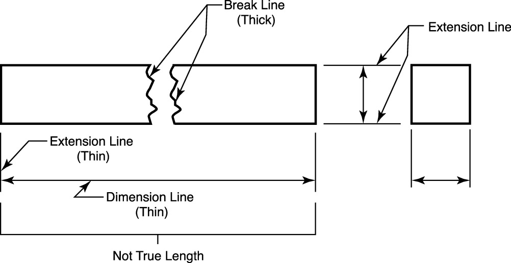
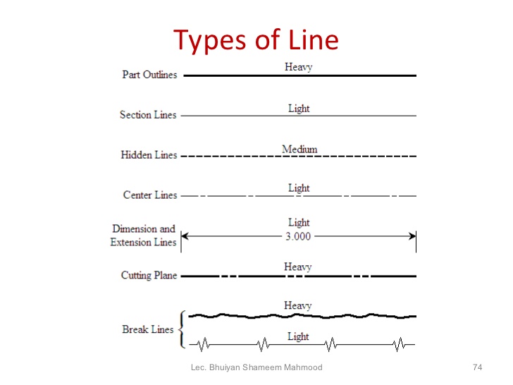
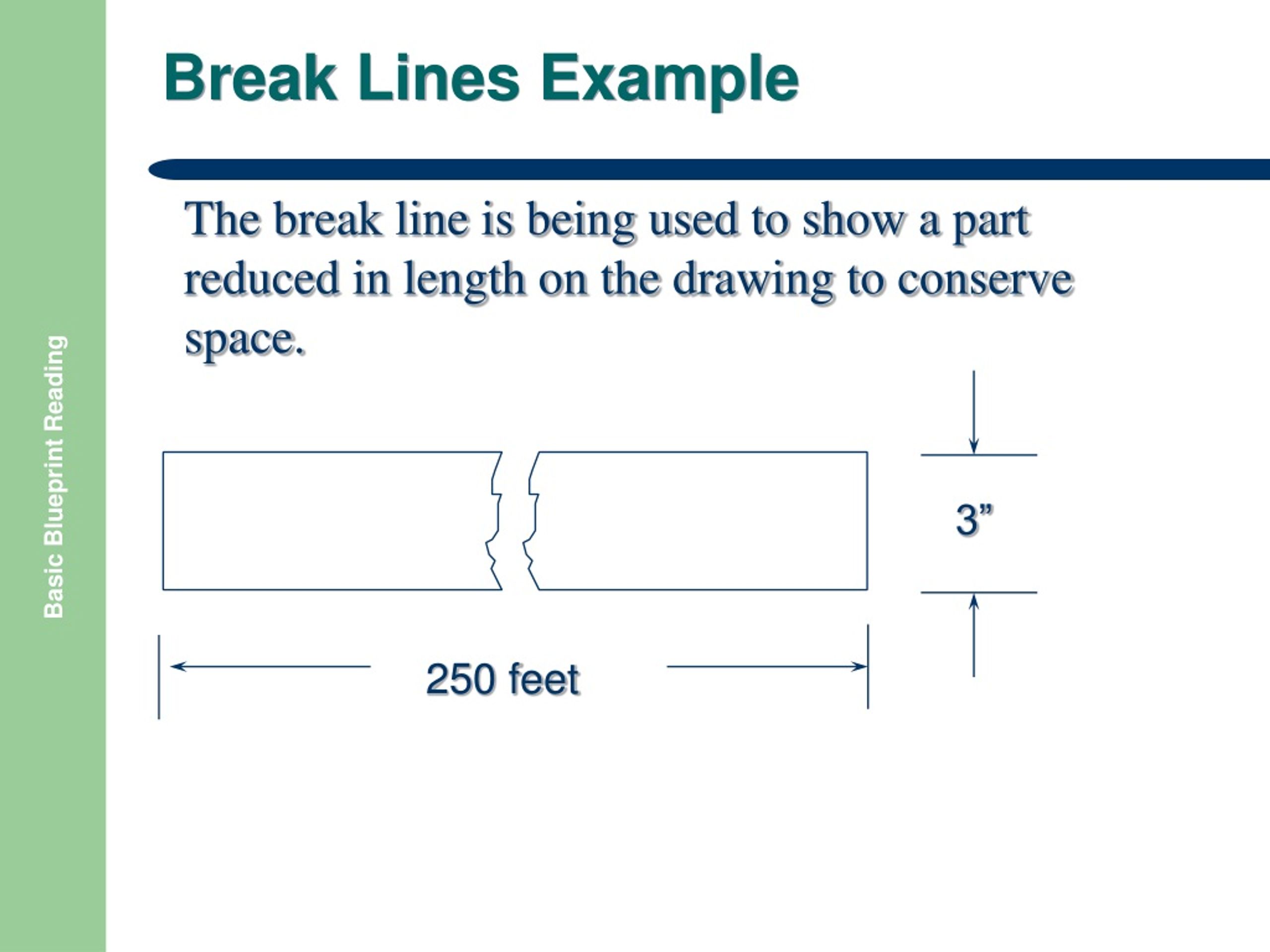
Web break lines are drawn to show that a part has been shortened to reduce its size on the drawing. A freehand thick line, and. The following is a detailed description of the above applications. Werk24’s artificial intelligence technology can help you by reading these break lines in technical drawings automatically. Curved lines (arcs, circles, and ellipses) cutting plane lines. Web break lines the size of the graphic representation of an object is often reduced (usually for the purpose of economizing on paper space) by the use of a device called a break. These types of lines also known as object lines. A long, ruled thin line with zigzags. It would be almost impossible for an engineer, designer, or architect to describe in words the shape, size, and relationship of a complex object. Visible lines are dark and thick.
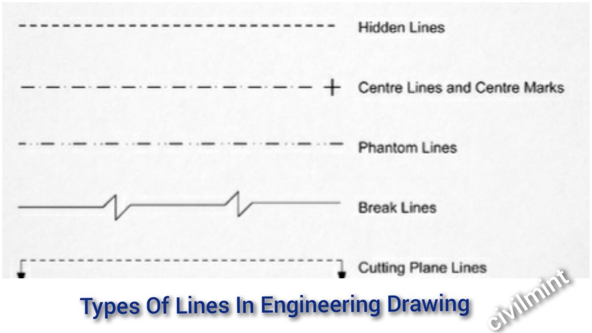
Curved lines (arcs, circles, and ellipses) cutting plane lines. The line type is usually continuous and the line weight is thin (0.3 mm). These lines are drawn to represent hidden or invisible edges of the objects. Recognizing such dashed lines while parsing drawings is reasonably straightforward if they are outlined with a ruler and compass but becomes challenging when they are hand. These line types are referred to as the alphabet of lines. *remember, any dimensions spanning over the break needs to have a dimension break indicated on the dimension line also. This line is used to show hidden edges of the main object. Web break lines are long and short lines with z breaks for flat objects and s breaks for round objects. Clear up your drawings in solidworks with break lines. In this highly interactive object, learners associate basic line types and terms with engineering drawing geometry.

Different Types of LINES in Engineering Drawing//Classification of
Break lines come in two forms: It would be almost impossible for an engineer, designer, or architect to describe in words the shape, size, and relationship of a complex object. Web do you want to understand the complexities involved in break lines of technical drawings? Curved lines (arcs, circles, and ellipses) cutting plane lines. Break lines are thin jagged lines.
short break line drawing examples pdf
Web break lines the size of the graphic representation of an object is often reduced (usually for the purpose of economizing on paper space) by the use of a device called a break. Break lines are used to shorten the size of a view for an exceptionally long part. These types of lines also known as object lines. Web do.

10 Different Types of Lines Used In Engineering Drawing
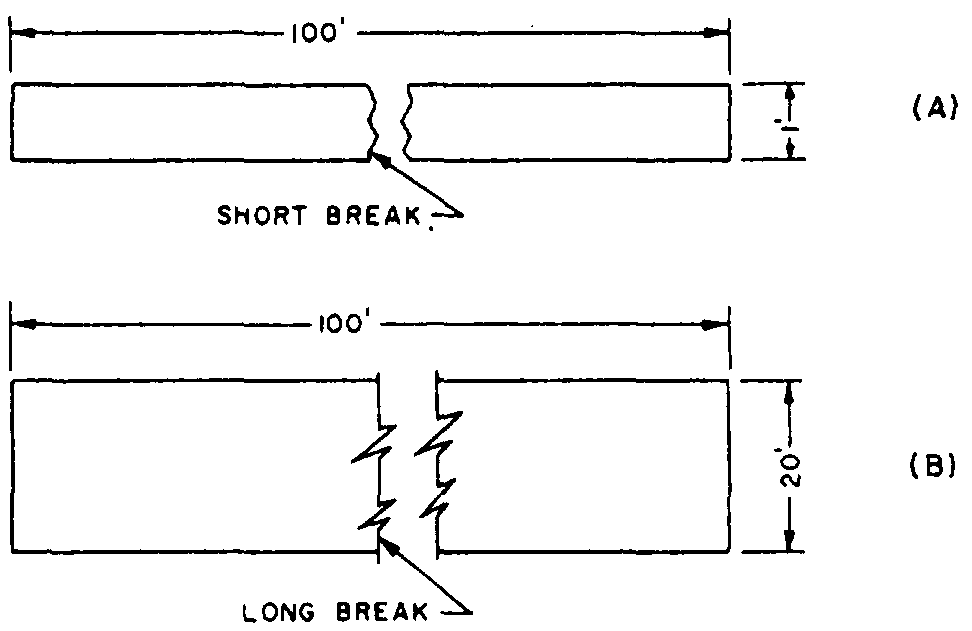
Break lines are thin jagged lines used to indicate a break in an object. Web break lines are long and short lines with z breaks for flat objects and s breaks for round objects. Solid, thick freehand lines are used for short break lines. Web basic types of lines used in engineering drawings. Thick or thin dashed line.

DRAWING BASICS
As the name suggest, they are visible in an engineering drawing. To represent the internal details of an assembly or. i have described each type of line briefly. Usually the first lines that you will use on a drawing are construction lines. The following is a detailed description of the above applications.
Types Of Lines In Engineering Drawing
Break lines are used to shorten the size of a view for an exceptionally long part. Standardized line types were developed for use in the industry. These types of lines also known as object lines. Hidden lined (thick) hidden lined (thick) type lines consist of thick short dashes, closely and evenly spaced. This line is used to show long break.

Engineering Drawing 2 Ch4 Conventional break YouTube
If you drew in the full length of the. These are the same lines that you used to lay out your drafting sheet. A long, ruled thin line with zigzags. Drawings can range from very simple, with just a few dimensions, to extremely complex, with multiple views and sheets and too many dimensions to count. Web break lines the size.
short break line drawing examples pdf
Web the continuous thin zigzag line shows a break line. Clear up your drawings in solidworks with break lines. Web break lines the size of the graphic representation of an object is often reduced (usually for the purpose of economizing on paper space) by the use of a device called a break. In this highly interactive object, learners associate basic.
Engineering Drawing 8 Tips to Improve Engineering Drawing Skills
Curved lines (arcs, circles, and ellipses) cutting plane lines. Standardized line types were developed for use in the industry. If yours fall into the first category, you might not have to do too much to display everything. Recognizing such dashed lines while parsing drawings is reasonably straightforward if they are outlined with a ruler and compass but becomes challenging when.
PPT BASIC BLUEPRINT READING PowerPoint Presentation, free download
A freehand thick line, and. Dimension and extension lines are. *remember, any dimensions spanning over the break needs to have a dimension break indicated on the dimension line also. Break lines reduce the size of drawings so they can be shown on smaller sheets of paper. They are 0.6 mm thick.

Types of Lines Engineering Drawing MechGate YouTube
Break lines are used to show imaginary breaks in objects. Web break lines are long and short lines with z breaks for flat objects and s breaks for round objects. Break lines are thin jagged lines used to indicate a break in an object. As the name suggest, they are visible in an engineering drawing. Web break lines are used.
*Remember, Any Dimensions Spanning Over The Break Needs To Have A Dimension Break Indicated On The Dimension Line Also.
By kelly curran glenn sokolowski. Usually the first lines that you will use on a drawing are construction lines. Hidden lined (thick) hidden lined (thick) type lines consist of thick short dashes, closely and evenly spaced. Web break lines are used to show where an object is broken to save drawing space or reveal interior features.
You Have Heard The Saying, “A Picture Is Worth A Thousand Words”.
Web this line is used to show short break or irregular boundaries. In this highly interactive object, learners associate basic line types and terms with engineering drawing geometry. These lines are drawn to represent hidden or invisible edges of the objects. The dashed line is used to indicate.
This Line Is Used To Show Long Break.
For each of these applications, we usually use different line types. They represent dashed lines, which are useful for various purposes. As the name suggest, they are visible in an engineering drawing. Web break lines are drawn to show that a part has been shortened to reduce its size on the drawing.
Hidden Lines Are 0.3 Mm Thin Dashed Line.
To represent the internal details of an assembly or. Suppose, for example, you want to make a drawing of a rectangle 1 ft wide by 100 ft long to the scale of 1/12, or 1 in. It would be almost impossible for an engineer, designer, or architect to describe in words the shape, size, and relationship of a complex object. Web the continuous thin zigzag line shows a break line.