Dimensioning In Engineering Drawing
Dimensioning In Engineering Drawing - Dimensions should be placed in the view which most clearly describes the feature being dimensioned. Web learn everything you need to know about dimensioning engineering drawings. Geometric dimensioning and tolerancing (gd&t) is a system of symbols and standards used in engineering drawings and models to specify the required form, size, orientation, and location of parts and features. Dimensioning is vital in the engineering industry as it ensures that the final product meets the required standards and specifications. 4.3 common mistakes and how to avoid them. What you’ll learn in this post: Web dimensioning a drawing is about adding dimension, notes, & lines to a drawing. While you may not be accustomed to reading dimensions from a technical drawing, you probably have had practice using dimensioning principles in your everyday life. It begins by defining dimensioning as specifying part sizes, locations, materials, tolerances and other information using figures, symbols and notes. Conventional parts (areas) abbreviations and symbols.
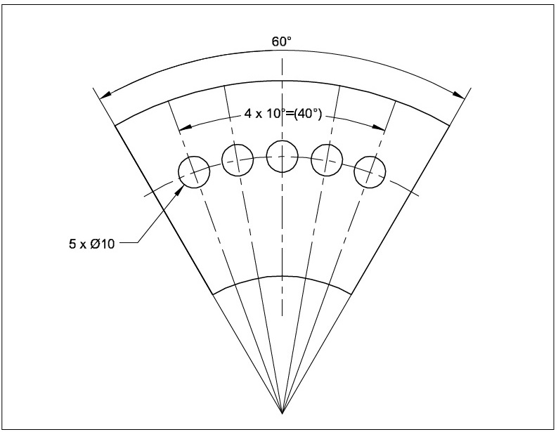
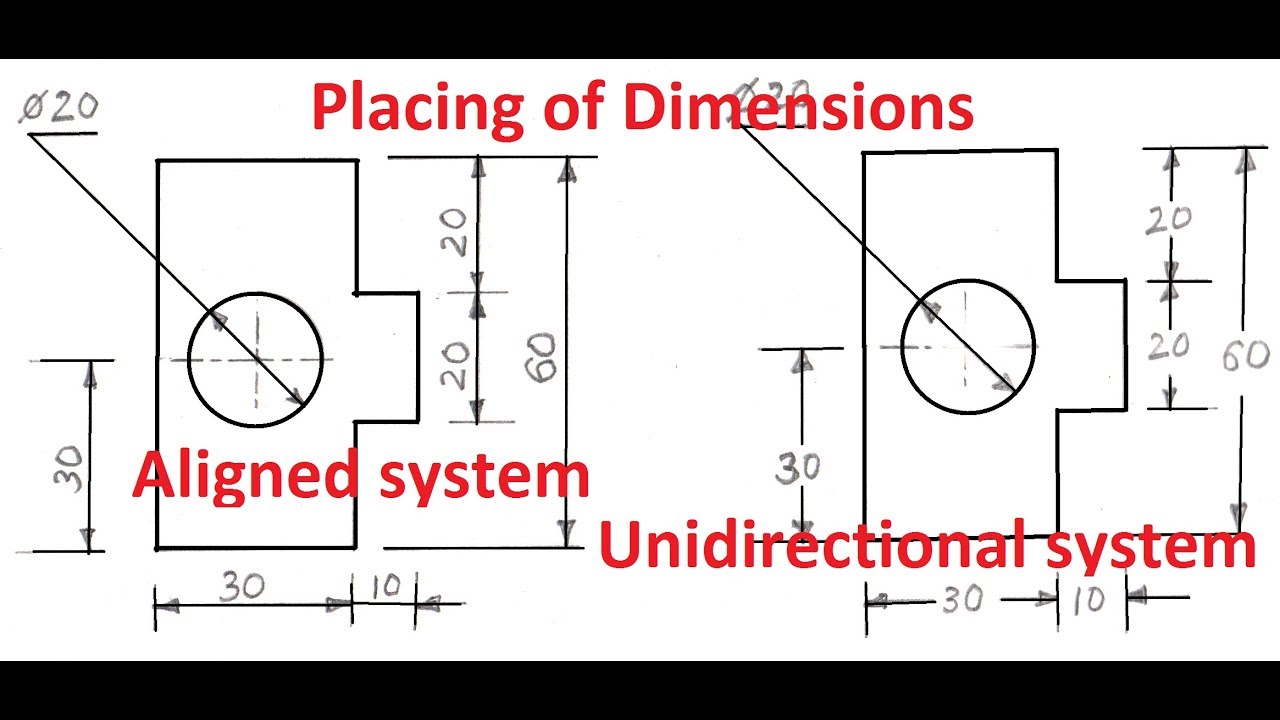
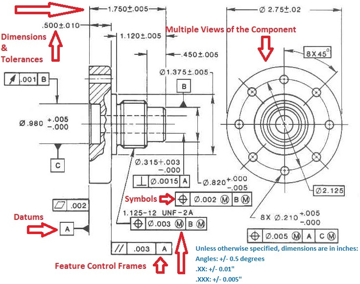
It begins by defining dimensioning as specifying part sizes, locations, materials, tolerances and other information using figures, symbols and notes. Web geometric dimensioning and tolerancing is a set of rules and gd&t symbols used on a drawing to communicate the intent of a design, focusing on the function of the part. Web learn everything you need to know about dimensioning engineering drawings. Web the new ipad pro — the thinnest apple product ever — features a stunningly thin and light design, taking portability to a whole new level. By kelly curran glenn sokolowski. It is an important tool for ensuring the interchangeability, functional accuracy, and reliability of manufactured components. One of the best ways to communicate one’s ideas is through some form of picture or drawing. Learners examine the basic types of dimensioning including unidirectional and aligned systems, and linear, aligned, angled, arrowless, chain, datum, chart, tabular, radius, diameter, typical, and reference dimensions. Dimensions and notations must be placed on the sketch where they can be clearly and easily read. Web basic types of dimensioning used in engineering drawings.
Dimensions and notations must be placed on the sketch where they can be clearly and easily read. Dimension elements dimensioning a drawing also identifies the tolerance (or accuracy) required for each dimension. Web 3.1 geometric shapes and their significance. Web systems of dimensioning and tolerancing. Engineering drawing of a machine tool part. Conventional parts (areas) abbreviations and symbols. Web learn the fundamental rules of dimensioning in engineering/architectural/structural drawings. By kelly curran glenn sokolowski. It then covers components of dimensioning like extension lines, dimension lines, leader lines and. Parallels, running, chains, & combined amplitude.
ENGINEERING DRAWING Dimensioning
Web in this video, we are going to learn about dimensions in engineering drawing! Conventional parts (areas) abbreviations and symbols. Web three principles of dimensioning must be followed: Extension line, dimension line, nominal value, and terminator. This youtube channel is dedicated to teaching people how to improve their technical drawing.

Types Of Dimensions In Engineering Drawing at GetDrawings Free download
Dimension elements dimensioning a drawing also identifies the tolerance (or accuracy) required for each dimension. 4.3 common mistakes and how to avoid them. By kelly curran glenn sokolowski. Some methods of dimensioning a drawing can produce an accumulated error. It then covers components of dimensioning like extension lines, dimension lines, leader lines and.

engineeringdrawing Dimensioning used in Engineering Drawing YouTube
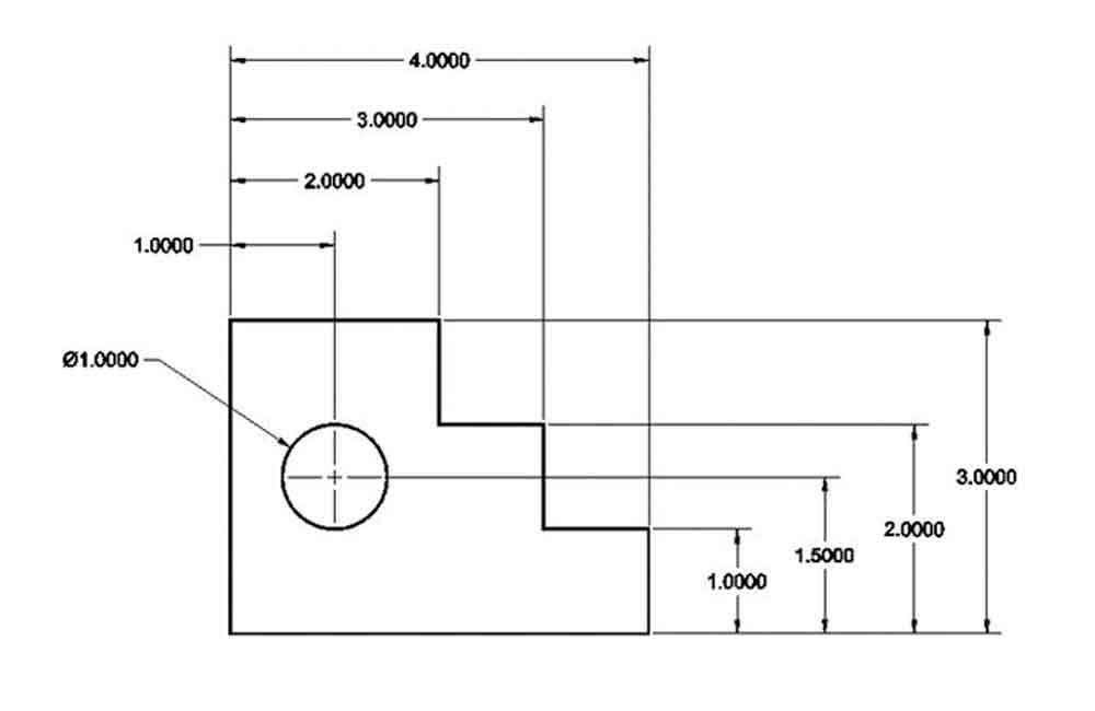
The cylinder is 1” ∅. Dimensions and notations must be placed on the sketch where they can be clearly and easily read. Do not leave any size, shape, or material in doubt. Web learn the fundamental rules of dimensioning in engineering/architectural/structural drawings. Engineering drawing of a machine tool part.
CivilSeek Everything you need to know about Civil Engineering.
Click on the links below to learn more about each gd&t symbol or concept, and be sure to download the free wall chart for a quick reference when at your desk or on the shop floor. Geometric dimensioning and tolerancing (gd&t) is a system of symbols and standards used in engineering drawings and models to specify the required form, size,.

METHOD OF DIMENSIONING ALIGNED METHOD II Engineering drawing II YouTube
Web a convenient guide for geometric dimensioning and tolerancing (gd&t) symbols at your fingertips. Learners examine the basic types of dimensioning including unidirectional and aligned systems, and linear, aligned, angled, arrowless, chain, datum, chart, tabular, radius, diameter, typical, and reference dimensions. Property indicators (symbols) rules for dimensioning. Web three principles of dimensioning must be followed: Some methods of dimensioning a.

Types Of Dimensions In Engineering Drawing at GetDrawings Free download
Web 3.1 geometric shapes and their significance. 4.2 tips for sketching, dimensioning, and detailing. Do not leave any size, shape, or material in doubt. 4.3 common mistakes and how to avoid them. Using gd&t results in a more accurate design, larger tolerances for less important design features, and cost savings for manufacturing.
Dimensioning and its role in drafting and design
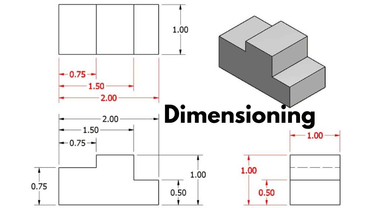
4.3 common mistakes and how to avoid them. Web dimensioning practice once the shape of a part is defined with an orthographic drawing (i.e., in projections), the size information is added in the form of dimensions. The base is ½” x 1 ½” square. Sections of objects with holes, ribs, etc. One of the best ways to communicate one’s ideas.
Dimensioning In Engineering Drawing Ppt
Our comprehensive guide covers techniques, standards, and best practices for accuracy and clarity. Web this document discusses dimensioning practices for engineering drawings. Web systems of dimensioning and tolerancing. The drilled through hole is ∅5/8”. Web essentially, dimensioning refers to the process of specifying the exact size, shape, and location of different parts and features on an engineering drawing.
Types Of Dimensions In Engineering Drawing at GetDrawings Free download
Geometric dimensioning and tolerancing (gd&t) is a system of symbols and standards used in engineering drawings and models to specify the required form, size, orientation, and location of parts and features. Double dimensioning of a feature is not permitted. It then covers components of dimensioning like extension lines, dimension lines, leader lines and. Parallels, running, chains, & combined amplitude. Web.

GENERAL RULES OF DIMENSIONING in Engineering Drawing YouTube
4.3 common mistakes and how to avoid them. Dimensions and notations must be placed on the sketch where they can be clearly and easily read. Learners examine the basic types of dimensioning including unidirectional and aligned systems, and linear, aligned, angled, arrowless, chain, datum, chart, tabular, radius, diameter, typical, and reference dimensions. Web systems of dimensioning and tolerancing. Do not.
It Begins By Defining Dimensioning As Specifying Part Sizes, Locations, Materials, Tolerances And Other Information Using Figures, Symbols And Notes.
Web basic types of dimensioning used in engineering drawings. The base is ½” x 1 ½” square. Conventional parts (areas) abbreviations and symbols. The angle begins as the midpoint of the 3” long dimension.
While You May Not Be Accustomed To Reading Dimensions From A Technical Drawing, You Probably Have Had Practice Using Dimensioning Principles In Your Everyday Life.
Dimensions should be placed in the view which most clearly describes the feature being dimensioned. Web dimensioning a drawing is about adding dimension, notes, & lines to a drawing. This is especially true for the engineer. Dimension elements dimensioning a drawing also identifies the tolerance (or accuracy) required for each dimension.
Parallels, Running, Chains, & Combined Amplitude.
Web every dimension must have an associated tolerance, and that tolerance must be clearly shown on the drawing. Engineering drawing of a machine tool part. Some methods of dimensioning a drawing can produce an accumulated error. 3.2 lines, angles, and dimensions.
One Of The Best Ways To Communicate One’s Ideas Is Through Some Form Of Picture Or Drawing.
Web the new ipad pro — the thinnest apple product ever — features a stunningly thin and light design, taking portability to a whole new level. Dimensions in engineering drawings are numerical values indicated graphically in a proper unit of measurement on engineering drawing with lines, symbols, and notes. Web this document discusses dimensioning practices for engineering drawings. Web geometric dimensioning and tolerancing is a set of rules and gd&t symbols used on a drawing to communicate the intent of a design, focusing on the function of the part.