Draw Mohrs Circle For The Stress State
Draw Mohrs Circle For The Stress State - Finding principal stresses and maximum shearing stresses using the mohr's circle method. Web to plot the circle, either use the calculated center c coordinate and the radius r, or directly plot the stress coordinates for two mutually perpendicular planes and draw the circle through the two points (a and b in illustration above) which must be diametrically opposite on the circle. (b) draw the mohr’s circle on the given graph. Web 1] draw a perpendicular line to the σn axis from the center ‘c’ of mohr’s circle. The state of plane stress at a point is represented by the stress element below. How good are you with this? In this video, we're going to take a look at stress transformation and mohr’s. The following two are good references, for examples. All points on the edge of the circle represent a possible state. With the definition (by mohr) of positive and negative shear:
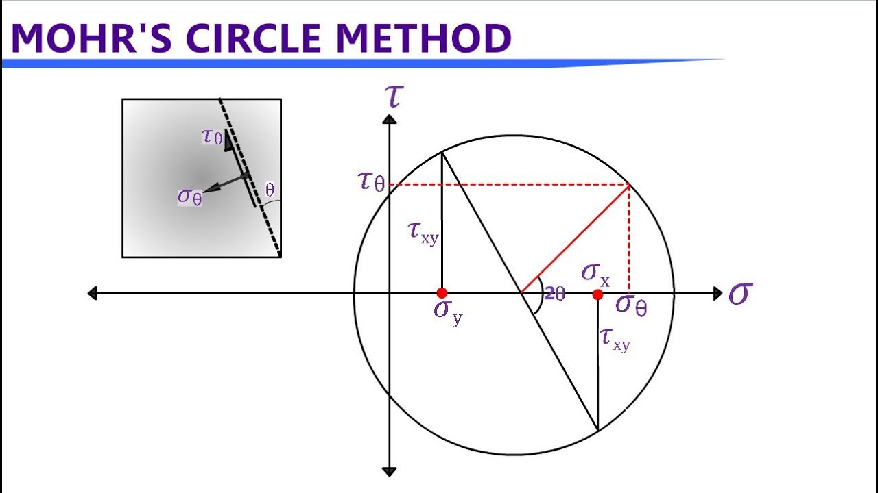
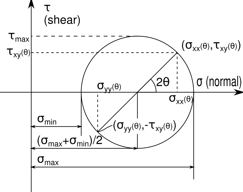
Mohr’s circle for stress diagram. The mohr's circle for plane strain can also be obtained from similar procedures. Computed principal stresses, their directions and maximum shear stress. This method is named as mohr’s circle and can be used to evaluate principal stress, maximum shear stresses and normal and tangential stresses at any plane. Web the equations for stress transformation actually describe a circle if we consider the normal stress 𝜎𝜎. All possible combinations of normal and shear stresses for the 3d stress element lie on the boundary of, or within, the shaded area. Mark the two stress states on mohr’s circle. Shear stress on y face: The figure depicts the state of plane stress at a point. Components of stress in 2d, mpa.
Divide ab at c (i.e., c is midway between a and b). With the definition (by mohr) of positive and negative shear: All points on the edge of the circle represent a possible state. This method is named as mohr’s circle and can be used to evaluate principal stress, maximum shear stresses and normal and tangential stresses at any plane. Mark the two stress states on mohr’s circle. The figure depicts the state of plane stress at a point. Given the following state of stress: Mohr’s circle calculator definition and formula. 80 mpa 80 mpa 50 mpa x y 50 mpa 25 mpa σ τ 15 2 80 50 2 =− − + = + = = x y c avg σ σ σ c a (θ=0) a b b (θ=90. Web the mohr's circle calculator provides an intuitive way of visualizing the state of stress at a point in a loaded material.
Mohr's Circle Stress Analysis for 2D & 3D cases YouTube
Web a and hoop stress h. Given the following state of stress: You can know about the theory of mohr's circles from any text books of mechanics of materials. 780k views 10 years ago mechanics of materials. Web the equations for stress transformation actually describe a circle if we consider the normal stress 𝜎𝜎.

How To Construct A Mohr's Circle Blog
A strip load of q = 900 lb/ft2 is applied over a width b. Web to plot the circle, either use the calculated center c coordinate and the radius r, or directly plot the stress coordinates for two mutually perpendicular planes and draw the circle through the two points (a and b in illustration above) which must be diametrically opposite.

Mohr's Circle Northwestern Mechatronics Wiki
Web a and hoop stress h. Determine the axial load p axing on the bar. Web the procedure of drawing a mohr's circle from a given stress state is discussed in the mohr's circle usage page. All points on the edge of the circle represent a possible state. Indicate on your drawing the following (5 points):
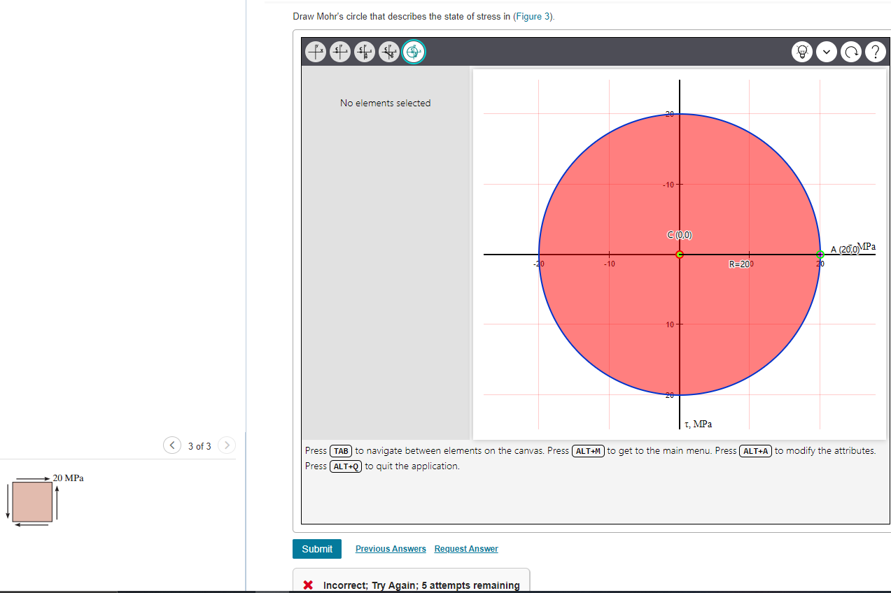
Solved Draw Mohr's circle that describes the state of stress
Specify the angle of the rotated element. Computed principal stresses, their directions and maximum shear stress. Part a draw mohr's circle for the stress state. It is named after christian otto mohr, who first introduced the concept in 1882. Web the equations for stress transformation actually describe a circle if we consider the normal stress 𝜎𝜎.

Mohr's Circle Normal and Tangential Stress, Principal Stress, Maximum
A strip load of q = 900 lb/ft2 is applied over a width b. 80 mpa 80 mpa 50 mpa x y 50 mpa 25 mpa σ τ 15 2 80 50 2 =− − + = + = = x y c avg σ σ σ c a (θ=0) a b b (θ=90. Part a draw mohr's circle for.

Mohr’s circle for two dimensional stress system YouTube
Draw a semicircle having its center at c and radius equal to ac or bc. Mohr’s circle for stress diagram. Sketch mohr's circle for stress. For the following state of stress.problem 2. (b) draw the mohr’s circle on the given graph.
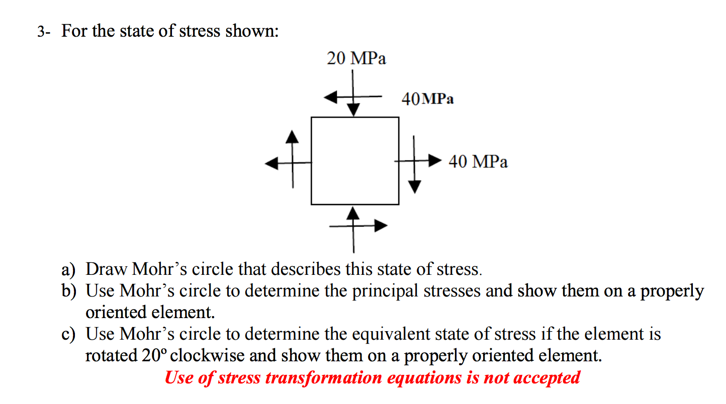
Solved For the state of stress shown Draw Mohr's circle
This video explains what mohr's circle is and how to draw it from a given state of stress. Mark the two stress states on mohr’s circle. 183k views 3 years ago mechanics of materials. Web the procedure of drawing a mohr's circle from a given stress state is discussed in the mohr's circle usage page. 941k views 4 years ago.
Mohr’s Circle Simplified What You Really Need to Know Mentored Engineer
80 mpa 80 mpa 50 mpa x y 50 mpa 25 mpa σ τ 15 2 80 50 2 =− − + = + = = x y c avg σ σ σ c a (θ=0) a b b (θ=90. 2θp,σ1,σ2, and τmax,minganscriptsaveplease help solve in matlab. (c) use mohr’s circle to determine (i) the principal stresses (σσσ 12 3,,),.
.svg)
Mohr's circle
2θp,σ1,σ2, and τmax,minganscriptsaveplease help solve in matlab. See the reference section for details on the methodology and the equations used. All points on the edge of the circle represent a possible state. (b) draw the mohr’s circle on the given graph. In this video, we're going to take a look at stress transformation and mohr’s.

Mohr Circle Principal Stress Mohr's Circle Stress state YouTube
Specify the angle of the rotated element. A strip load of q = 900 lb/ft2 is applied over a width b. Indicate on your drawing the following (5 points): Stress plane stress and coordinate transformations. 2] find the value of shear stress at the point where the perpendicular line cuts the mohr’s circle.
Sketch Mohr's Circle For Stress.
Web 1] draw a perpendicular line to the σn axis from the center ‘c’ of mohr’s circle. Computed principal stresses, their directions and maximum shear stress. Web the equations for stress transformation actually describe a circle if we consider the normal stress 𝜎𝜎. In this video, we're going to take a look at stress transformation and mohr’s.
Web German Physicist Otto Mohr Developed A Method To Graphically Interpret The General State Of Stress At A Point.
The figure depicts the state of plane stress at a point. Web mechanical engineering questions and answers. The state of plane stress at a point is represented by the stress element below. Mohr’s circle for stress diagram.
This Method Is Named As Mohr’s Circle And Can Be Used To Evaluate Principal Stress, Maximum Shear Stresses And Normal And Tangential Stresses At Any Plane.
(c) use mohr’s circle to determine (i) the principal stresses (σσσ 12 3,,), and the absolute maximum shear stress max τabs. The following two are good references, for examples. Components of stress in 2d, mpa. Web to draw a mohr's circle for a given 2d stress state with normal stresses ( \sigma_ {xx} σxx and \sigma_ {yy} σyy) and shear stresses ( \tau_ {xy} τ xy and \tau_ {yx} τ yx ):
Web Mohr’s Circle Is Used To Calculate The Shear Strength Of The Soil.
Specify the angle of the rotated element. 780k views 10 years ago mechanics of materials. (ii) the stresses in the directions perpendicular (n) and tangent (t) to the weld. Figure 1) select the center of mohr's circle and select the point that represents the reference point (oz, tzy).