Draw The Shear And Bending Moment Diagrams For The Beam
Draw The Shear And Bending Moment Diagrams For The Beam - Web shear and moment diagrams are graphs which show the internal shear and bending moment plotted along the length of the beam. In each problem, let x be the distance measured from left end of the beam. Web in this chapter, the student will learn how to determine the magnitude of the shearing force and bending moment at any section of a beam or frame and how to present the computed values in a graphical form, which is referred to as the “shearing force” and the “bending moment diagrams.” You'll get a detailed solution from a subject matter expert that helps you learn core concepts. In general the process goes like this: The beginning, end, or change of a load pattern. Draw the shear force, axial force and bending moment diagrams. Web understanding shear force and bending moment diagrams. Description of the device 1 is the beam 2 is the load hanger 3 is the shear force load hanger 4 is the bending moment load hanger where: Draw the axial force, shearing force, and bending moment diagram for the structure, noting the sign conventions discussed in.
Web compute the principal values of the shearing force and the bending moment at the segment where the section lies. In general the process goes like this: Description of the device 1 is the beam 2 is the load hanger 3 is the shear force load hanger 4 is the bending moment load hanger where: Web write shear and moment equations for the beams in the following problems. You'll get a detailed solution from a subject matter expert that helps you learn core concepts. Assume that the flexural rigidity is a multiple of ei and differs for each member as shown in the figure. Web draw the shear force and bending moment diagrams for the cantilever beam supporting a concentrated load of 5 lb at the free end 3 ft from the wall. David roylance department of materials science and engineering massachusetts institute of technology cambridge, ma 02139 november 15, 2000. Draw the axial force, shearing force, and bending moment diagram for the structure, noting the sign conventions discussed in. Without there being any load applied to the beam, check that the beam is in its equilibrium position.
This beam calculator is designed to help you calculate and plot the bending moment diagram (bmd), shear force diagram (sfd), axial force diagram. Web the first step in calculating these quantities and their spatial variation consists of constructing shear and bending moment diagrams, \(v(x)\) and \(m(x)\), which are the internal shearing forces and bending moments induced in. They allow us to see where the maximum loads occur so that we can optimize the design to prevent failures and reduce the overall weight and cost of the structure. We go through breaking a beam into segments, and then we learn about the relationships between shear force. Draw the shear force, axial force and bending moment diagrams. Web understanding shear force and bending moment diagrams. Web this problem has been solved! Web calculate the reactions at the supports of a beam, frame and truss. In each problem, let x be the distance measured from left end of the beam. Shear and bending moment diagrams.

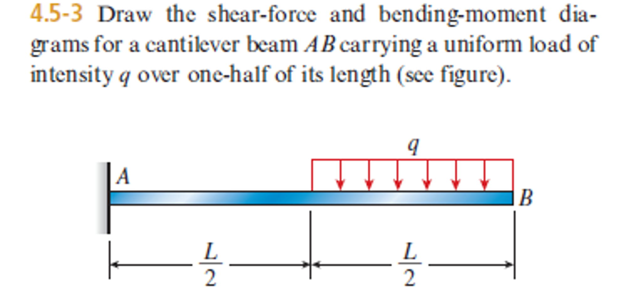
Bending moment and shear force diagram of a cantilever beam
Adjust the tension springs if necessary. The beginning, end, or change of a load pattern. In each problem, let x be the distance measured from left end of the beam. Loading tends to cause failure in two main ways: Web draw the shear force and bending moment diagrams for the cantilever beam supporting a concentrated load of 5 lb at.

Shear force & Bending moment diagram for Overhanging Beam YouTube
Web shear force and bending moment diagrams are analytical tools used in conjunction with structural analysis to help perform structural design by determining the value of shear forces and bending moments at a given point of a structural element such as a beam. Determine all the reactions on the beam. Write answers in the space provided. Description of the device.

Solved Draw The Shearforce And Bendingmoment Diagrams F...
Draw the shear and moment diagrams for the beam. Web calculate the reactions at the supports of a beam, frame and truss. Web learn to draw shear force and moment diagrams using 2 methods, step by step. Civil engineering questions and answers. Web shear and moment diagrams are graphs which show the internal shear and bending moment plotted along the.

Learn How To Draw Shear Force And Bending Moment Diagrams Engineering
Shear and moment diagrams and formulas are excerpted from the western woods use book, 4th edition, and are provided herein as a courtesy of. Draw the axial force, shearing force, and bending moment diagram for the structure, noting the sign conventions discussed in. Draw the shear force, axial force and bending moment diagrams. X 1 = 0.15m x 2 =.

Shear Force and Bending Moment diagram of Beam with Triangular Load
Figures 1 through 32 provide a series of shear and moment diagrams with accompanying formulas for design of beams under various static loading conditions. Web our calculator generates the reactions, shear force diagrams (sfd), bending moment diagrams (bmd), deflection, and stress of a cantilever beam or simply supported beam. Web shear and moment diagrams are graphs which show the internal.
Solved Draw the shearforce and bendingmoment diagrams for
5 lb 12 lb 5 lb 5 lb e c d b 9 in. Shear and moment diagrams and formulas are excerpted from the western woods use book, 4th edition, and are provided herein as a courtesy of. Web learn to draw shear force and moment diagrams using 2 methods, step by step. Loading tends to cause failure in two.

Learn How To Draw Shear Force And Bending Moment Diagrams Engineering
They allow us to see where the maximum loads occur so that we can optimize the design to prevent failures and reduce the overall weight and cost of the structure. The beginning, end, or change of a load pattern. In each problem, let x be the distance measured from left end of the beam. This beam calculator is designed to.
Shear force and bending moment diagram practice problem 8 YouTube
Web this problem has been solved! Web this video explains how to draw shear force diagram and bending moment diagram with easy steps for a simply supported beam loaded with a concentrated load. Shear force and bending moment are examples of interanl forces that are induced in a structure when loads are applied to that structure. Web shear force and.

Cantilever Beam Shear Force & Bending Moment Diagram YouTube
20 kn 40 kn/m cl 150 kn m 8 m 3 m prob. Web shear force and bending moment diagrams are powerful graphical methods that are used to analyze a beam under loading. This beam calculator is designed to help you calculate and plot the bending moment diagram (bmd), shear force diagram (sfd), axial force diagram. Draw the shear and.

Brief Information About Shear Force And Bending Moment Diagrams
X 1 = 0.15m x 2 = 0.10m x 3 = 0.05m a = 0.105m step 1: Web write shear and moment equations for the beams in the following problems. This page will walk you through what shear forces and bending moments are, why they are useful, the procedure for drawing the diagrams and some other keys aspects as well..
In General The Process Goes Like This:
Web our calculator generates the reactions, shear force diagrams (sfd), bending moment diagrams (bmd), deflection, and stress of a cantilever beam or simply supported beam. X 1 = 0.15m x 2 = 0.10m x 3 = 0.05m a = 0.105m step 1: Draw the shear force, axial force and bending moment diagrams. Determine all the reactions on the beam.
This Page Will Walk You Through What Shear Forces And Bending Moments Are, Why They Are Useful, The Procedure For Drawing The Diagrams And Some Other Keys Aspects As Well.
Skyciv also has a free beam calculator for you to calculate bending moment diagrams fast and easily. Draw the shear and moment diagrams for the beam. Assume that the flexural rigidity is a multiple of ei and differs for each member as shown in the figure. Web this is an example problem that will show you how to graphically draw a shear and moment diagram for a beam.
Loading Tends To Cause Failure In Two Main Ways:
There are 4 steps to solve this one. Shear force and bending moment are examples of interanl forces that are induced in a structure when loads are applied to that structure. Also, draw shear and moment diagrams, specifying values at all change of loading positions and at. Web the first step in calculating these quantities and their spatial variation consists of constructing shear and bending moment diagrams, \(v(x)\) and \(m(x)\), which are the internal shearing forces and bending moments induced in.
Web Calculate The Reactions At The Supports Of A Beam, Frame And Truss.
They allow us to see where the maximum loads occur so that we can optimize the design to prevent failures and reduce the overall weight and cost of the structure. Shear and moment diagrams and formulas are excerpted from the western woods use book, 4th edition, and are provided herein as a courtesy of. 1) calculate support reactions 2). Draw a fbd of the structure