Draw The Shear And Moment Diagrams For The Beam
Draw The Shear And Moment Diagrams For The Beam - This problem has been solved! You'll get a detailed solution from a subject matter expert that helps you learn core concepts. Solve for all external forces and moments, create a free body diagram, and create the shear diagram. Web statics last updated: Web the first step in calculating these quantities and their spatial variation consists of constructing shear and bending moment diagrams, \(v(x)\) and \(m(x)\), which are the internal shearing forces and bending moments induced in. This video explains how to draw shear force diagram and bending moment diagram with easy steps for a simply. Determine all the reactions on the beam. Web you will be fully competent in drawing shear force and bending moment diagrams for statically determinate beams and frames. Web you'll get a detailed solution from a subject matter expert that helps you learn core concepts. Beams are structural elements primarily designed to support vertical loads.
Web you'll get a detailed solution from a subject matter expert that helps you learn core concepts. Solve for all external forces and moments, create a free body diagram, and create the shear diagram. Web draw the shear and moment diagrams for the beam, and determine the shear and moment in the beam as functions of x for 0 x 4 ft, 4 ft x 10 ft, and 10 ft x 14 ft 250 lb 250 lb 150 lb/ft 6 ft 4 ft 4 ft prob. There are 4 steps to solve this one. Shear and moment diagrams and formulas are excerpted from the western woods use book, 4th edition, and are provided herein as a courtesy of. Web to create the moment diagram for a shaft, we will use the following process. 5/117 draw the shear and moment diagrams for the beam shown. Web beam guru.com is a online calculator that generates bending moment diagrams (bmd) and shear force diagrams (sfd), axial force diagrams (afd) for any statically determinate (most simply supported and cantilever beams) and statically indeterminate beams, frames and trusses. Web you will be fully competent in drawing shear force and bending moment diagrams for statically determinate beams and frames. Shear force and bending moment diagrams are powerful graphical methods that are used to analyze a beam under loading.
Also, draw the shear force diagram (sfd) and the bending moment diagram (bmd). How to use skyciv beam calculator. Solve for all external forces and moments, create a free body diagram, and create the shear diagram. In general the process goes like this: Web you'll get a detailed solution from a subject matter expert that helps you learn core concepts. This problem has been solved! Advanced physics questions and answers. Shear and moment diagrams and formulas are excerpted from the western woods use book, 4th edition, and are provided herein as a courtesy of. Civil engineering questions and answers. The beginning, end, or change of a load pattern.

Solved Draw the shear and moment diagrams for the beam.
Web below is a simple example of what shear and moment diagrams look like, afterwards, the relation between the load on the beam and the diagrams will be discussed. Draw the shear and moment diagrams for the beam. Web shear and moment equations and diagrams for beams. 5/117 draw the shear and moment diagrams for the beam shown. Web draw.

Shear force and bending moment diagrams for beams pdf
Web 1) calculate the shear force and bending moment for the beam subjected to concentrated load as shown in the figure. How to use skyciv beam calculator. Internal forces in beams and frames, libretexts. There are 4 steps to solve this one. This problem has been solved!
Solved Draw the shear and moment diagrams for the beam using
Determine the maximum bending moment mmax and its location. Web learning by teaching. Solve for all external forces and moments, create a free body diagram, and create the shear diagram. Also, draw shear and moment diagrams, specifying values at all change of loading positions and at. In each problem, let x be the distance measured from left end of the.

Learn How To Draw Shear Force And Bending Moment Diagrams Engineering
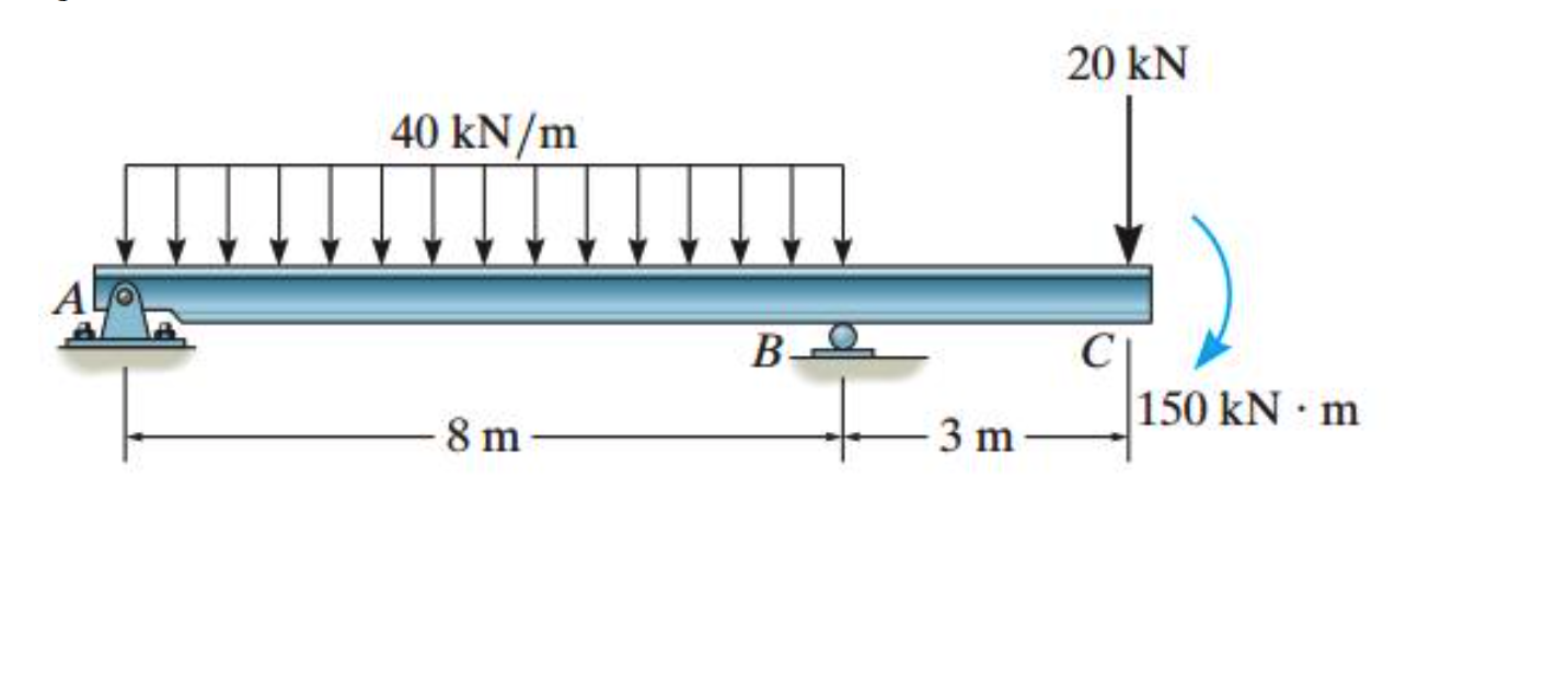
Determine the distance b, measured from the left end, to the point where the bending moment is zero between the supports 100 lb/ft 6' 3' problem 5/117 answer b 4.5 ft. Web calculate shear force diagrams. You will have a robust system of analysis that allows you to confidently tackle the analysis of. 20 kn 40 kn/m cl 150 kn.

Learn How To Draw Shear Force And Bending Moment Diagrams Engineering
20 kn 40 kn/m cl 150 kn m 8 m 3 m prob. Also, draw the shear force diagram (sfd) and the bending moment diagram (bmd). Web learning by teaching. Web draw the shear and moment diagrams for the beam, and determine the shear and moment throughout the beam as functions of x. Beams are structural elements primarily designed to.

Learn How To Draw Shear Force And Bending Moment Diagrams Engineering
Lined up below the shear diagram, draw a set of axes. Web 92k views 3 years ago statics. Web draw the shear and moment diagrams for the beam, and determine the shear and moment throughout the beam as functions of x. Web you'll get a detailed solution from a subject matter expert that helps you learn core concepts. Web shear.

Solved Draw the shear and moment diagrams for the beam
4 r ay = 40. Divide the beam (of length l) into n segments. Web the first step in calculating these quantities and their spatial variation consists of constructing shear and bending moment diagrams, \(v(x)\) and \(m(x)\), which are the internal shearing forces and bending moments induced in. Also, draw shear and moment diagrams, specifying values at all change of.

Draw the shear and moment diagrams for the beam.
Web you'll get a detailed solution from a subject matter expert that helps you learn core concepts. You'll get a detailed solution from a subject matter expert that helps you learn core concepts. This problem has been solved! In general the process goes like this: You'll get a detailed solution from a subject matter expert that helps you learn core.

Drawing Shear and Moment Diagrams for Beam YouTube
Web draw the shear and moment diagrams for the beam subjected to the two point loads. Web draw the shear and moment diagrams for the beam, and determine the shear and moment in the beam as functions of x for 0 x 4 ft, 4 ft x 10 ft, and 10 ft x 14 ft 250 lb 250 lb 150.

Shear and moment diagrams geekloki
Civil engineering questions and answers. Web you'll get a detailed solution from a subject matter expert that helps you learn core concepts. Web calculate shear force diagrams. Internal forces in beams and frames, libretexts. Determine the distance b, measured from the left end, to the point where the bending moment is zero between the supports 100 lb/ft 6' 3' problem.
We Go Through Breaking A Beam Into Segments, And Then We Learn About The Relationships Between Shear Force.
Shear and bending moment diagrams. 11k views 2 years ago statics. How to use skyciv beam calculator. Determine all the reactions on the beam.
200Lb 100Lb 250Lb 100Lb 0 250 Lbrc
Web draw the shear and moment diagrams for the beam, and determine the shear and moment in the beam as functions of x for 0 x 4 ft, 4 ft x 10 ft, and 10 ft x 14 ft 250 lb 250 lb 150 lb/ft 6 ft 4 ft 4 ft prob. Draw the shear and moment diagrams for the beam 9k n/m 9 kn/m in 3 m. Determine the distance b, measured from the left end, to the point where the bending moment is zero between the supports 100 lb/ft 6' 3' problem 5/117 answer b 4.5 ft. This page will walk you through what shear forces and bending moments are, why they are useful, the procedure for drawing the diagrams and some other keys aspects as well.
Web Below Is A Simple Example Of What Shear And Moment Diagrams Look Like, Afterwards, The Relation Between The Load On The Beam And The Diagrams Will Be Discussed.
Web you'll get a detailed solution from a subject matter expert that helps you learn core concepts. Web draw the shear and moment diagrams for the beam subjected to the two point loads. Shear and bending moment equations. Solve for all external forces and moments, create a free body diagram, and create the shear diagram.
Colorado State University Via Engineeringstatics.
Shear and moment diagrams and formulas are excerpted from the western woods use book, 4th edition, and are provided herein as a courtesy of. In each problem, let x be the distance measured from left end of the beam. Also, draw shear and moment diagrams, specifying values at all change of loading positions and at. (45in.) 100 lb(15in.) 250 lb(20 in.) 100 lb(55in.) 0r 200 lbre fryc 0: