Draw The Shear Force And Bending Moment Diagram
Draw The Shear Force And Bending Moment Diagram - Draw a fbd of the structure. (see above) sum up the forces in the vertical direction. W0 = 5000 n/m, p = 100 kn, t = 15 mm, l = 15 m, material = steel, r. Web identified q&as 1. Web being able to draw shear force diagrams (sfd) and bending moment diagrams (bmd) is a critical skill for any student studying statics, mechanics of materials, or structural engineering. Consider a simple beam shown of length l that carries a uniform load of w (n/m) throughout its length and is held in equilibrium by reactions r 1 and r 2. Shear force value will remain same up to point load. The bending moment at a section of a beam. Web reactions of support · shear force diagrams · bending moment diagrams · deflection and span ratios · cantilever & simply supported beam. This example is an extract from this course.
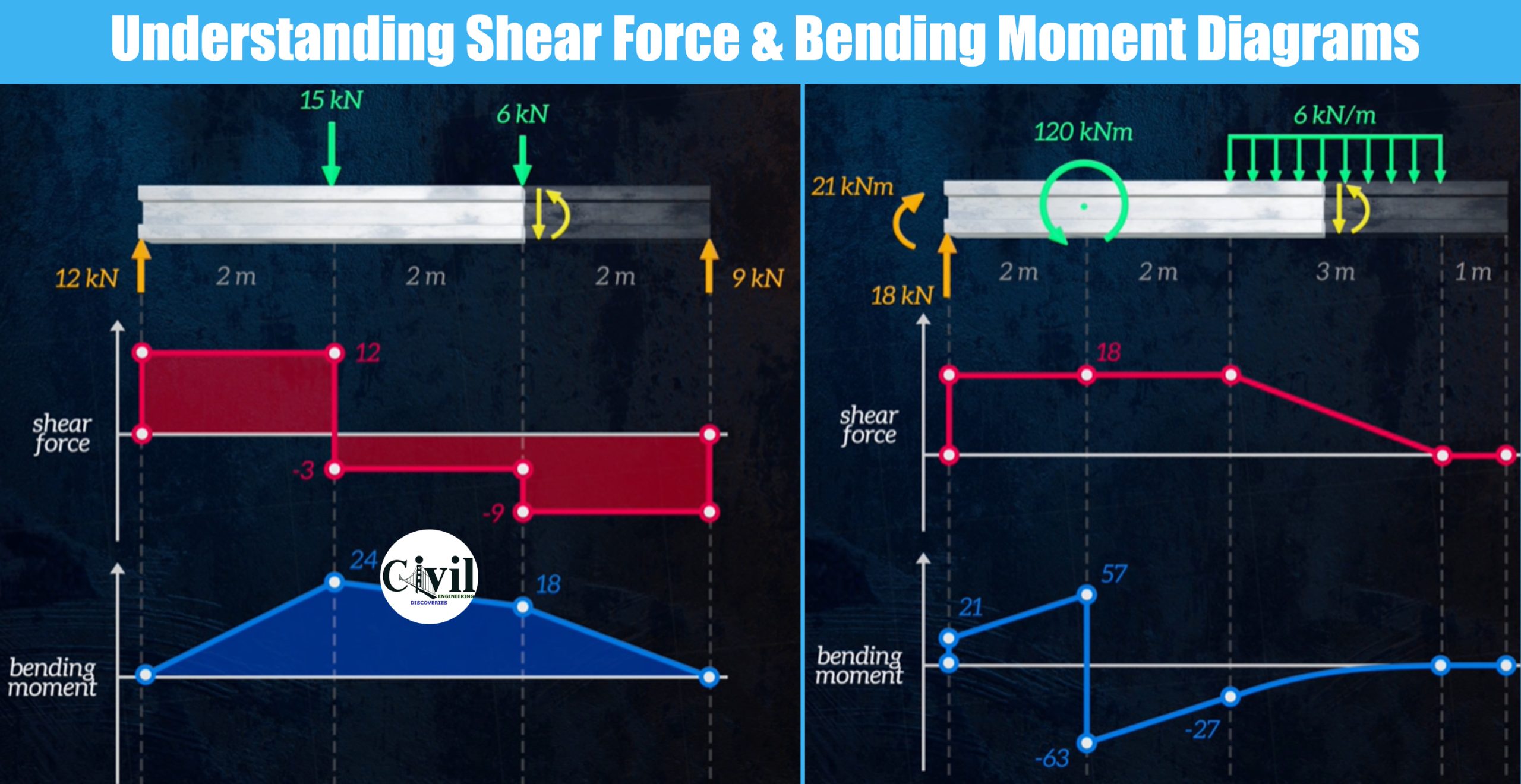
They allow us to see where the maximum loads occur so that we can optimize the design to prevent failures and reduce the overall weight and cost of the structure. Just a quick heads up, if you’re new to shear force and bending moment diagrams, this question. Calculate the maximum compressive stress, maximum tensile stress, shear stress, maximum deflection, shear centre, and buckling load (pcr). Web steps to construct shear force and bending moment diagrams. Web draw the shear force and bending moment diagrams for the cantilever beam supporting a concentrated load of 5 lb at the free end 3 ft from the wall. Determine new origin (x n) and use positive sign conventions to. Web shear and moment diagrams. These diagrams can be used to easily determine the type, size, and material of a. Web now find value of shear force at point a, b and c. Now that we have a grasp of the fundamentals, let’s see how it all ties together with a bigger more complex worked example.
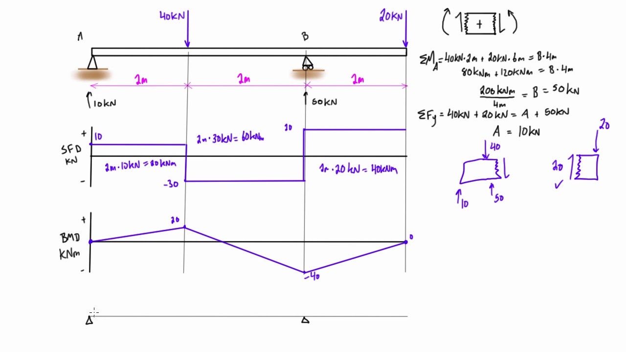
(see above) sum up the forces in the vertical direction. Value of shear force at point load changes and remain same until any other point load come into action. Draw a fbd of the structure. These diagrams can be used to easily determine the type, size, and material of a. Draw a free body diagram of the beam with global coordinates (x); From left to right, make “cuts” before and after each reaction/load. Draw the axial force, shear force, and bending moment diagram for the structure shown in figure. A diagram showing the variation of the shear force along a beam is called the shear force diagram. When drawing the bending moment diagram you will need to work out the bending moment just before and just after point c: Finally calculating the moments can be done in the following steps:

Shear Force and Bending Moment Diagram Calculator
Royal melbourne institute of technology. Shear force and bending moment diagram example #1: Civil engineering questions and answers. Find the shear forces and bending moment at the critical points. We go through breaking a beam into segments, and then we learn about the relatio.

Cantilever Beam Shear Force & Bending Moment Diagram YouTube
Web draw the shear force and bending moment diagrams for the cantilever beam supporting a concentrated load of 5 lb at the free end 3 ft from the wall. Determine new origin (x n) and use positive sign conventions to. Web shear and moment diagrams are graphs which show the internal shear and bending moment plotted along the length of.
Shear force and bending moment diagram practice problem 8 YouTube
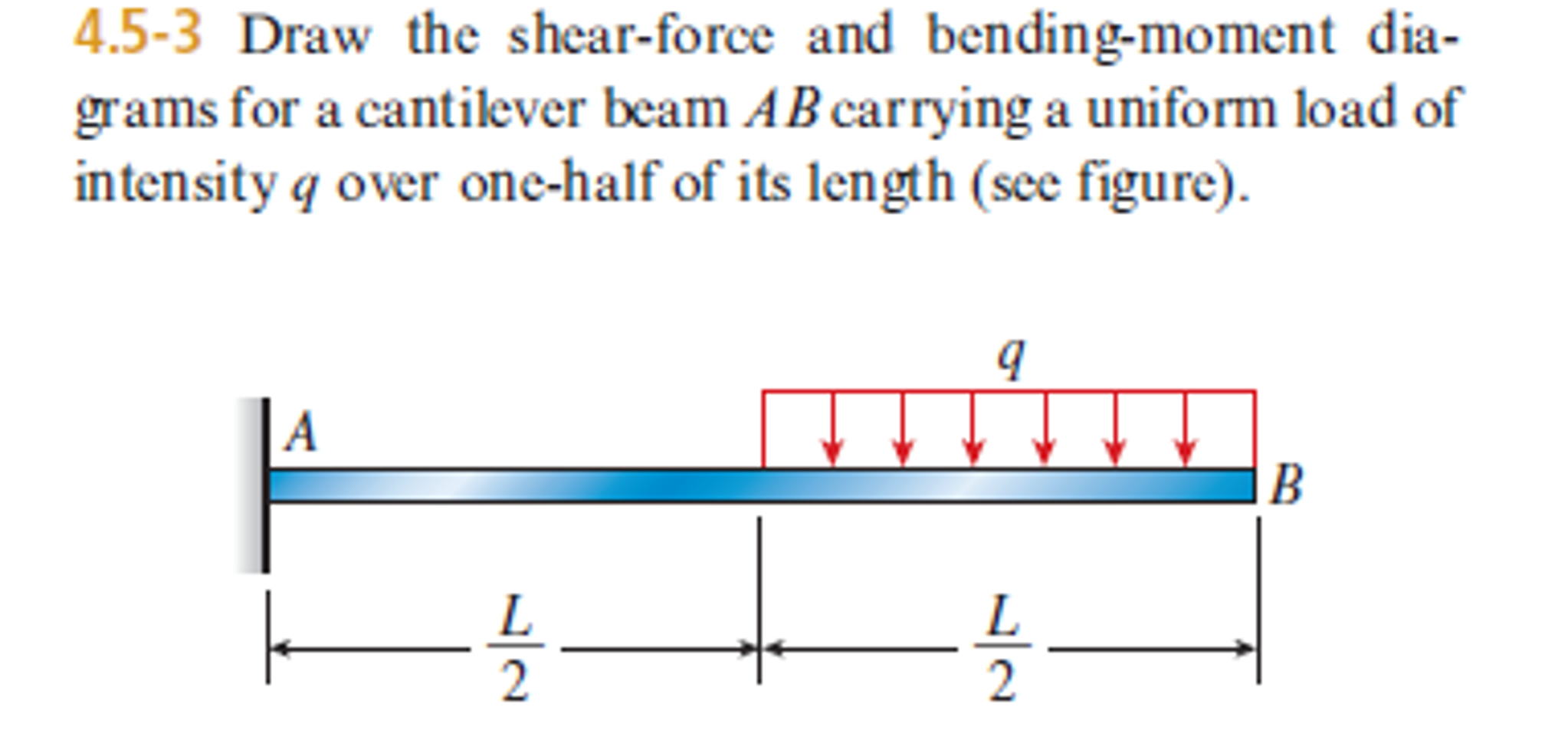
Web draw the shear force and bending moment diagrams for the cantilever beam supporting a concentrated load of 5 lb at the free end 3 ft from the wall. Since beams primarily support vertical loads the axial. Web shear force and bending moment diagrams are analytical tools used in conjunction with structural analysis to help perform structural design by determining.
Understanding Shear Force And Bending Moment Diagrams Engineering
Finally calculating the moments can be done in the following steps: Wall reactions for the cantilevered beam. Shear force value will remain same up to point load. Draw the axial force, shear force, and bending moment diagram for the structure shown in figure. D) draw shear force and bending moment diagrams.

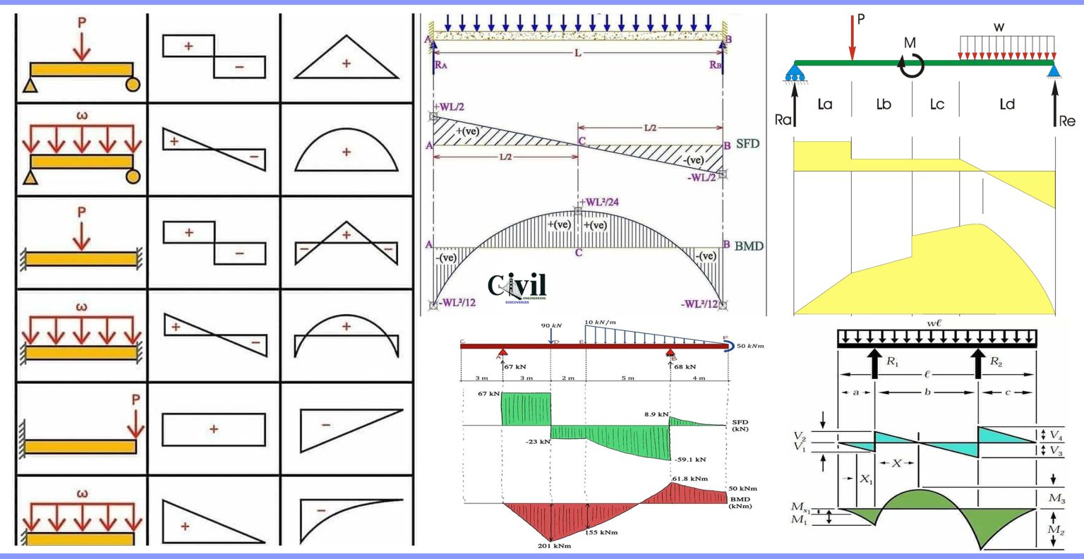
Shear force & Bending Moment Formulas With Diagram CCAL Shear force
A diagram showing the variation of the shear force along a beam is called the shear force diagram. D) draw shear force and bending moment diagrams. From left to right, make “cuts” before and after each reaction/load. Draw a fbd of the structure. In this experiment, we will work on drawing the shear and bending diagram of a beam.

Shear force and bending moment diagram practice problem 3 YouTube
Assume that the beam is cut at point c a distance of x from he left support and the portion of the beam to the right of c be removed. W0 = 5000 n/m, p = 100 kn, t = 15 mm, l = 15 m, material = steel, r. We go through breaking a beam into segments, and then.
Solved Draw the shearforce and bendingmoment diagrams for
Web reactions of support · shear force diagrams · bending moment diagrams · deflection and span ratios · cantilever & simply supported beam. Using the machine in figure 1, we will measure the shear force and bending moment of a beam after subjecting it to given loads. Just a quick heads up, if you’re new to shear force and bending.

Learn How To Draw Shear Force And Bending Moment Diagrams Engineering
Consider a simple beam shown of length l that carries a uniform load of w (n/m) throughout its length and is held in equilibrium by reactions r 1 and r 2. Draw shear force and bending moment diagrams.a) Since beams primarily support vertical loads the. Web being able to draw shear force diagrams (sfd) and bending moment diagrams (bmd) is.

Brief Information About Shear Force And Bending Moment Diagrams
By drawing the free body diagram you identify all of these loads and show then on a sketch. When simply supported beam is carrying point loads. This example is an extract from this course. Shear force and bending moment diagram example #2: Web shear and moment diagrams.
Brief Information About Shear Force And Bending Moment Diagrams
Web learn to draw shear force and moment diagrams using 2 methods, step by step. Then find shear force value in sections. Web draw the shear force and bending moment diagrams for the cantilever beam supporting a concentrated load of 5 lb at the free end 3 ft from the wall. We go through breaking a beam into segments, and.
This Example Is An Extract From This Course.
How to draw sfd and bmd for a simply supported beam? Assume that the beam is cut at point c a distance of x from he left support and the portion of the beam to the right of c be removed. Web this is the easiest way to draw shear force diagram and bending moment diagram. Calculate the maximum compressive stress, maximum tensile stress, shear stress, maximum deflection, shear centre, and buckling load (pcr).
Calculate The Reaction Forces Using Equilibrium Equations ( ∑ Forces = 0 And ∑ Moments = 0 );
Web egr2312 lab experiment n°8 shearing and bending moment diagrams 1. Web shear and moment diagrams. Since beams primarily support vertical loads the axial. Finally calculating the moments can be done in the following steps:
In This Experiment, We Will Work On Drawing The Shear And Bending Diagram Of A Beam.
W0 = 5000 n/m, p = 100 kn, t = 15 mm, l = 15 m, material = steel, r. To calculate the bending moment of a beam, we must work in the same way we did for. Shear force and bending moment diagram example #2: Web beamguru.com is a online calculator that generates bending moment diagrams (bmd) and shear force diagrams (sfd), axial force diagrams (afd) for any statically determinate (most simply supported and cantilever beams) and statically indeterminate beams, frames and trusses.the calculator is fully customisable to suit most beams,.
Web Shear And Moment Diagrams Are Graphs Which Show The Internal Shear And Bending Moment Plotted Along The Length Of The Beam.
When drawing the bending moment diagram you will need to work out the bending moment just before and just after point c: Web you can just ignore point c when drawing the shear force diagram. They allow us to see where the maximum loads occur so that we can optimize the design to prevent failures and reduce the overall weight and cost of the structure. Web being able to draw shear force diagrams (sfd) and bending moment diagrams (bmd) is a critical skill for any student studying statics, mechanics of materials, or structural engineering.