Drawing A Bode Plot
Drawing A Bode Plot - Web to use the bode plot calculator follow these steps: Generate a root locus plot: A bode plot consists of two separate plots, one for. Review how get a transfer function for a circuit. Next, identify the factors like k, poles and zeros at the. Find the poles and zeros. The plot displays the magnitude (in db) and phase (in degrees) of the system. Web making the bode plots for a transfer function involve drawing both the magnitude and phase plots. Draw the overall bode diagram by adding up the results from part 3. H(jw) 1 w j + 1 1 + j w z2 = a(w) + p1.
Choose the independent variable used in the transfer function. Firstly, write the given transfer function in the time constant form. Review how get a transfer function for a circuit. Web bode’s gain phase relationship. The magnitude is plotted in decibels (db) and the phase is plotted in. In this video, i have solved an example on how to sketch the bode magnitude and phase plot. Web a bode plot is a graph commonly used in control system engineering to determine the stability of a control system. A bode plot consists of two separate plots, one for. Separate the transfer function into its constituent parts. Draw the overall bode diagram by adding up the results from part 3.
In this video, i have solved an example on how to sketch the bode magnitude and phase plot. Web making the bode plots for a transfer function involves drawing both the magnitude and phase plots. The magnitude is plotted in decibels (db) while the phase is plotted in. Separate the transfer function into its constituent parts. Find the poles and zeros. Choose the type of bode plot you. Web an online bode plot grapher is presented. To draw bode diagram there are four steps: Draw the overall bode diagram by adding up the results from part 3. Choose the independent variable used in the transfer function.

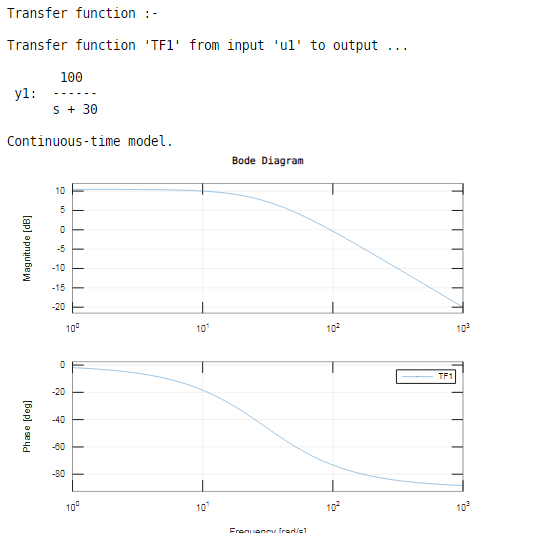
Bode Plot Example Bode Diagram Example MATLAB Electrical Academia
Next, identify the factors like k, poles and zeros at the. Web making the bode plots for a transfer function involves drawing both the magnitude and phase plots. Draw the bode diagram for each part. H(jw) 1 w j + 1 1 + j w z2 = a(w) + p1. A bode plot maps the frequency response of.

Bode plot Wikiwand
Web a bode plot is a graph commonly used in control system engineering to determine the stability of a control system. In this video, i have solved an example on how to sketch the bode magnitude and phase plot. Choose the independent variable used in the transfer function. Choose the type of bode plot you. Write the transfer function of.

ME 340 Example Drawing Bode Plot of a Transfer Function 2 YouTube
In this video, i have solved an example on how to sketch the bode magnitude and phase plot. Draw the bode diagram for each part. Generate a root locus plot: Next, identify the factors like k, poles and zeros at the. Find why magnitude and phase plots are a.

Bode Plot EXAMPLE YouTube
H(jw) 1 w j + 1 1 + j w z2 = a(w) + p1. Write the transfer function of the circuit in the form. Choose the independent variable used in the transfer function. Web making the bode plots for a transfer function involves drawing both the magnitude and phase plots. Next, identify the factors like k, poles and zeros.

simple method to draw bode plot3 YouTube
H(jw) 1 w j + 1 1 + j w z2 = a(w) + p1. Web an online bode plot grapher is presented. How to put the transfer function into a standard form. A bode plot maps the frequency response of. Web bode’s gain phase relationship.

How To Draw Bode Plot Phase Diagram
Review how get a transfer function for a circuit. Web a bode plot is a graph commonly used in control system engineering to determine the stability of a control system. Find why magnitude and phase plots are a. Draw the bode diagram for each part. The plot displays the magnitude (in db) and phase (in degrees) of the system.
Bode Plot Matlab How to do Bode Plot Matlab with examples?
Rewrite the transfer function in proper form. 506k views 7 years ago bode plot. To draw bode diagram there are four steps: H(jw) 1 w j + 1 1 + j w z2 = a(w) + p1. The magnitude is plotted in decibels (db) and the phase is plotted in.

Bode Plot Example Bode Diagram Example MATLAB Electrical Academia
1.1m views 11 years ago classical control. In this video, i have solved an example on how to sketch the bode magnitude and phase plot. Choose the type of bode plot you. The input to the calculator is the transfer function h (s) h ( s), where s = jω s = j ω with j = √−1 j =.

Some features of the Bode plot of a complex lead compensator. The Bode
Draw the bode diagram for each part. In this video, i have solved an example on how to sketch the bode magnitude and phase plot. Web bode’s gain phase relationship. Separate the transfer function into its constituent parts. Find why magnitude and phase plots are a.

how to draw bode plot in MATLAB Bode plot using MATLAB MATLAB
Review how get a transfer function for a circuit. Rewrite the transfer function in proper form. Write the transfer function of the circuit in the form. The input to the calculator is the transfer function h (s) h ( s), where s = jω s = j ω with j = √−1 j = − 1 and ω ω is.
Web Making The Bode Plots For A Transfer Function Involve Drawing Both The Magnitude And Phase Plots.
Web bode plots give engineers a way to visualize the effect of their circuit, in terms of voltage magnitude and phase angle (shift). H(jw) 1 w j + 1 1 + j w z2 = a(w) + p1. Web bode’s gain phase relationship. A bode plot maps the frequency response of.
The Magnitude Is Plotted In Decibels (Db) And The Phase Is Plotted In.
Web the steps to sketch the bode plot are as follows: Review how get a transfer function for a circuit. 506k views 7 years ago bode plot. Next, identify the factors like k, poles and zeros at the.
The Input To The Calculator Is The Transfer Function H (S) H ( S), Where S = Jω S = J Ω With J = √−1 J = − 1 And Ω Ω Is The Angular Frequency In.
Web a bode plot is a graph commonly used in control system engineering to determine the stability of a control system. Root locus plot for transfer function (s+2)/ (s^3+3s^2+5s+1) have a question about using wolfram|alpha?. Bode(sys) creates a bode plot of the frequency response of a dynamic system model sys. Generate a root locus plot:
Rewrite The Transfer Function In Proper Form.
The magnitude is plotted in decibels (db) while the phase is plotted in. Draw the overall bode diagram by adding up the results from part 3. Find the poles and zeros. Firstly, write the given transfer function in the time constant form.