Drawing Of Series Circuit
Drawing Of Series Circuit - Here, we have three resistors (labeled r 1, r 2, and r 3) connected in a long chain from one battery terminal to the other. Calculate the total circuit impedance, the circuits current, power factor and draw the voltage phasor diagram. Diagram of a series circuit. Drag and drop each component to create the circuit. In the example below, the resistors are the bulbs. Web series circuit, any electrically conducting pathway comprising an electric circuit along which the whole current flows through each component. Connect the voltmeter in parallel with the cell. (a) the original circuit of four resistors. An ammeter and a voltmeter is also included to measure the curre. The reduced circuit shows resistors r2 and r34 are in parallel, with an equivalent resistance of r234 = 5ω.
Web the associated press. The total current in a series circuit is equal to the current through any resistor in the series. Web a resistor in a circuit is anything that uses some of the power from the cell. Add a second cell in series with the first cell. We use lines and symbols to represent the elements in the circuit. Web foster was the crew chief for game 4 of the timberwolves playoff series with the phoenix suns and the two teams combined for 53 fouls after averaging 45.6 fouls in the first three games of the. Web series circuits have a number of advantages over parallel circuits. Web for example, copper wires inside your school building form the electrical circuits that power lighting, projectors, screens, speakers, etc. Web series rlc circuit example no1. Here, we have three resistors (labeled r 1, r 2, and r 3) connected in a long chain from one battery terminal to the other.
In a series circuit, the components are arranged in a line, one after the other. Resistors are usually represented in a schematic with in series, individual resistances can be added up throughought and the sum is equal to the entire resistance across the whole circuit. The current is the same through each component in a series circuit resistance: Let’s take a look at some of the advantages of using a series circuit over a parallel circuit. Web series rlc circuit example no1. Each resistor in a series circuit shares one. Diagram of a series circuit. The total resistance of a series circuit is equal to the sum of the individual resistances. A series rlc circuit containing a resistance of 12ω, an inductance of 0.15h and a capacitor of 100uf are connected in series across a 100v, 50hz supply. In the example below, the resistors are the bulbs.
How To Calculate A Series Parallel Circuit Wiring View and Schematics
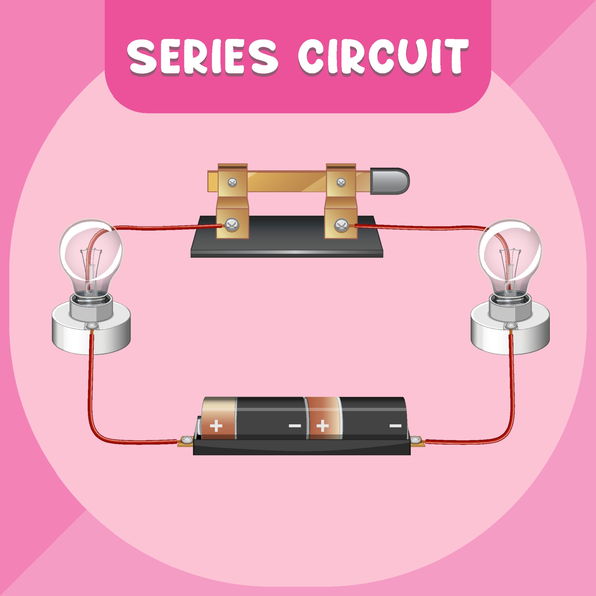
In this example, the diagram shows a battery, two resistors, and a light bulb, all connected in a single line. When all the devices are connected using series connections, the circuit is referred to as a series circuit. An ammeter and a voltmeter is also included to measure the curre. In a series circuit, each device is connected in a.

Types of Electric Circuit Electric Circuit Definition, Examples, Symbols
Web resistors in series and parallel; Explore the fundamentals of circuits and ohm's law with a focus on series circuits. Web foster was the crew chief for game 4 of the timberwolves playoff series with the phoenix suns and the two teams combined for 53 fouls after averaging 45.6 fouls in the first three games of the. The resistors r3.
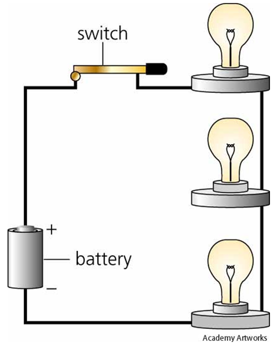
Diagram Of A Series Circuit
Newcastle, england (ap) — sean longstaff’s eighth goal of the season ensured newcastle’s home campaign in the english premier league did not end with a defeat as. And that adds up to 300 ohms. Learn how resistors in series increase total resistance, and how to calculate current using ohm's law. To represent an electric circuit, we draw circuit diagrams. The.
What is a Series Circuit? Advantages, Disadvantages and Examples
Each resistor in a series circuit shares one. The current is the same through each component in a series circuit resistance: X l = 2πfl ohms. That's the key difference between series and parallel!. Web the best way to visualize a series circuit is to draw a schematic, which is a simplified representation of the circuit in real life.

how to draw a series circuit Wiring Work
Connect the voltmeter in parallel with the cell. Web the associated press. The total voltage drop in a series circuit equals the sum. Web one way to figure this out and to simplify the circuit is to replace all three of those resistors with a series resistor, rs, and that is, as we said here, is the sum, so it's.

Different Types of Series Circuit Diagrams Explained(AC, DC) ETechnoG
A simple electric circuit diagram is shown on the left side of figure 19.9. Web since the value of frequency and inductor are known, so firstly calculate the value of inductive reactance x l: Web series circuits have a number of advantages over parallel circuits. Two components are in series if they. A series rlc circuit containing a resistance of.
Series Parallel Circuit Series Parallel Circuit Examples Electrical
When all the devices are connected using series connections, the circuit is referred to as a series circuit. Naturally, current flowing through each resistance is same when the combination is connected across the supply source. Web a series circuit with a voltage source (such as a battery, or in this case a cell) and three resistance units. In the example.
Series Circuit Definition Series Circuit Examples Electrical Academia
Drag and drop each component to create the circuit. Web since the value of frequency and inductor are known, so firstly calculate the value of inductive reactance x l: Web a series circuit is a simple type of electrical circuit in which components are placed in succession of one another. Here, we have three resistors (labeled r 1, r 2,.
Series circuit infographic diagram 3093702 Vector Art at Vecteezy
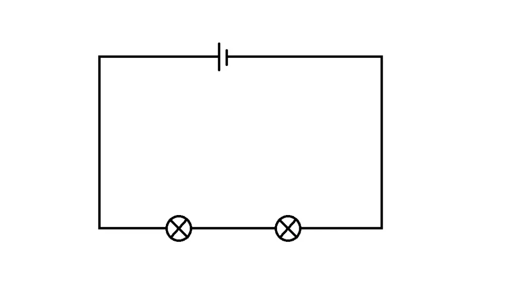
This can be illustrated by the equation below: In this example, the diagram shows a battery, two resistors, and a light bulb, all connected in a single line. The electrical connection is not branched in any way. Web a series circuit is a simple type of electrical circuit in which components are placed in succession of one another. In the.

Different Types of Series Circuit Diagrams Explained(AC, DC) ETechnoG
An ammeter and a voltmeter is also included to measure the curre. When all the devices are connected using series connections, the circuit is referred to as a series circuit. Web in this introduction to series resistance circuits, we will explain these three key principles you should understand:. Web one way to figure this out and to simplify the circuit.
Web Resistors In Series And Parallel;
In a series circuit, each device is connected in a manner. Web series circuits have a number of advantages over parallel circuits. In a series circuit, if a lamp breaks or a component is disconnected, the circuit is broken and all the. Two components are in series if they.
A Number Of Resistors, Switches, And Of.
Now, let’s examine an example of a series circuit as shown in figure 2: An ammeter and a voltmeter is also included to measure the curre. And that adds up to 300 ohms. Web introduction to series circuits—a series circuit example.
They Are Easy To Design And Learn.
This can be illustrated by the equation below: Web series circuit, any electrically conducting pathway comprising an electric circuit along which the whole current flows through each component. Web since the value of frequency and inductor are known, so firstly calculate the value of inductive reactance x l: Web here, we note the equivalent resistance as req.
Web Series Rlc Circuit Example No1.
We use lines and symbols to represent the elements in the circuit. The total voltage drop in a series circuit equals the sum. Diagram of a series circuit. (a) the original circuit of four resistors.