Drawing Series Circuit
Drawing Series Circuit - The total voltage drop in a series circuit equals the sum of the individual voltage drops. Each time there is damage (break) in any one of the resistors, the entire circuit will not function. Web circuit diagram is a free application for making electronic circuit diagrams and exporting them as images. Examine the circuit diagram to make this assessment. Web a series circuit consists of several resistances, connected one after the other in such a way that they form a chain (fig. She will cover everything from wires, light bulbs, switches, and resistors. Bodechon will teach you the basic symbols used to draw electrical circuits. Web to recognize a series circuit, to distinguish it from a parallel circuit, and to construct and/or interpret a schematic diagram of a series circuit. Explore the fundamentals of circuits and ohm's law with a focus on series circuits. Now pick three spots along the wire.
She will cover everything from wires, light bulbs, switches, and resistors. Web series rlc circuit example no1. Examine the circuit diagram to make this assessment. If you follow a series circuit from one side to the other you will pass through all of the different components without any branches. Each time there is damage (break) in any one of the resistors, the entire circuit will not function. Web to recognize a series circuit, to distinguish it from a parallel circuit, and to construct and/or interpret a schematic diagram of a series circuit. Learn how resistors in series increase total resistance, and how to calculate current using ohm's law. Then she will have you try to draw. The total resistance of a series circuit is equal to the sum of the individual resistances. A circuit in series only has one loop that can be.
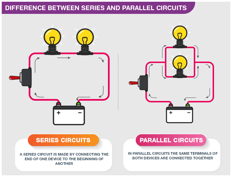
Web series rlc circuit example no1. As mentioned in the previous section of lesson 4, two or more electrical devices in a circuit can be connected by series connections or by parallel connections. The total voltage drop in a series circuit equals the sum of the individual voltage drops. The electrical connection is not branched in any way. A series rlc circuit containing a resistance of 12ω, an inductance of 0.15h and a capacitor of 100uf are connected in series across a 100v, 50hz supply. Introduction to series circuits—a series circuit example. To compare the values of current and electric potential at various locations within a series circuit and to explain the principles that form the basis of such comparisons. Each time there is damage (break) in any one of the resistors, the entire circuit will not function. Examine the circuit diagram to make this assessment. Web what is a series circuit?
What is Series Circuit? Definition & Calculation Linquip
Introduction to series circuits—a series circuit example. A series rlc circuit containing a resistance of 12ω, an inductance of 0.15h and a capacitor of 100uf are connected in series across a 100v, 50hz supply. To compare the values of current and electric potential at various locations within a series circuit and to explain the principles that form the basis of.
Series and Parallel Circuits SparkFun Learn
Calculate the total circuit impedance, the circuits current, power factor and draw the voltage phasor diagram. Circuit symbols and circuit diagrams. The schematic drawing is a better way to draw a series circuit. Web determine whether resistors are in series, parallel, or a combination of both series and parallel. Use the appropriate list of major features for series or parallel.
Series circuit infographic diagram 3093702 Vector Art at Vecteezy
The electrical connection is not branched in any way. Web circuit diagram is a free application for making electronic circuit diagrams and exporting them as images. Explore the fundamentals of circuits and ohm's law with a focus on series circuits. We’ll then explore what happens in series and parallel circuits when The total voltage drop in a series circuit equals.
How To Draw Series Circuit Diagrams
Each time there is damage (break) in any one of the resistors, the entire circuit will not function. The schematic drawing is a better way to draw a series circuit. Parallel resistors (part 1) parallel resistors (part 2) parallel resistors (part 3) parallel conductance. The total resistance of a series circuit is equal to the sum of the individual resistances..

Parts Of A Simple Circuit
The schematic drawing is a better way to draw a series circuit. Without changing the settings, allow the simulation to run for 20 s while you count the number of electrons passing through that spot. This physics tutorial explains how to draw a series circuit made up of a lamp and a. Science > electrical engineering > circuit analysis >.

Types of Electric Circuit Series Circuit, Parallel Circuit Define
To compare the values of current and electric potential at various locations within a series circuit and to explain the principles that form the basis of such comparisons. Typically, complex circuits are not arranged in nice, neat, clean schematic diagrams for us to follow. Now pick three spots along the wire. Science > electrical engineering > circuit analysis > Web.
How To Get Voltage In A Series Circuit Wiring Diagram
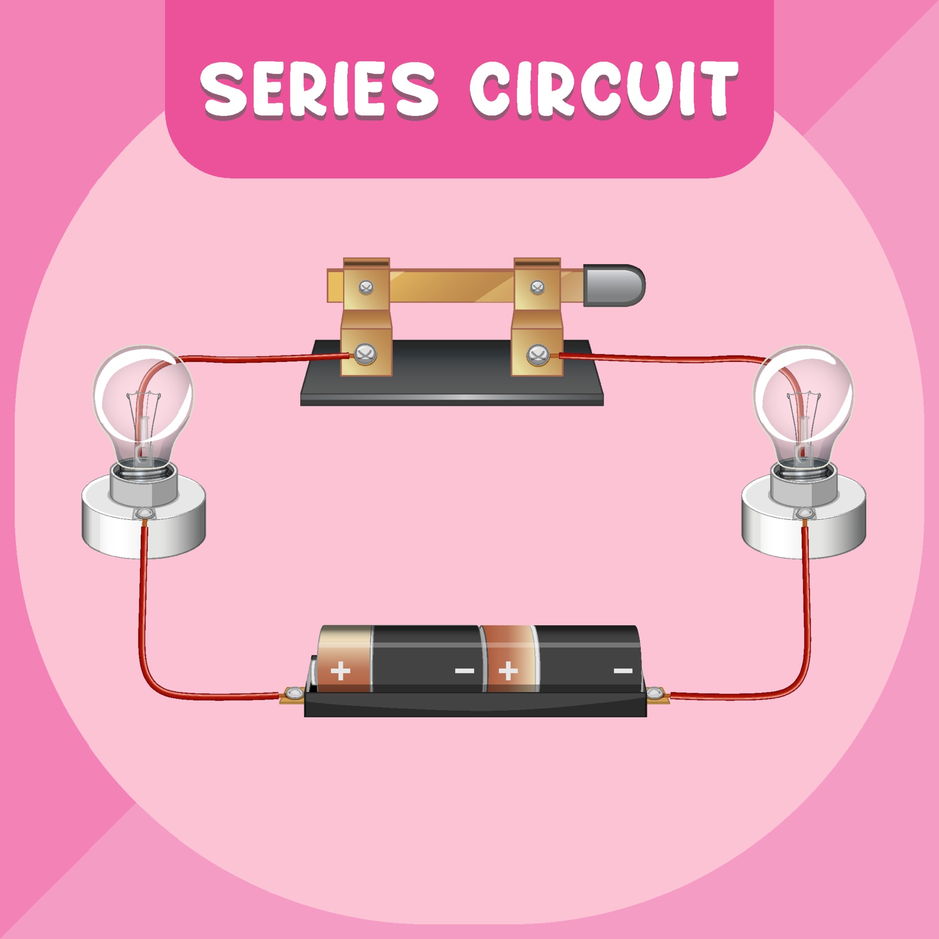
Web series rlc circuit example no1. Web a series circuit is a simple type of electrical circuit in which components are placed in succession of one another. The total resistance of a series circuit is equal to the sum of the individual resistances. Web a series circuit consists of several resistances, connected one after the other in such a way.

Images Of Series And Parallel Circuit Diagrams Zoya Circuit
Each time there is damage (break) in any one of the resistors, the entire circuit will not function. Web determine whether resistors are in series, parallel, or a combination of both series and parallel. When we talk about visualizing a series circuit, think of. They are often drawn in such a way that makes it difficult to follow which components.
Series Parallel Circuit Series Parallel Circuit Examples Electrical
In this video we will look at a series circuit. The electrical connection is not branched in any way. To compare the values of current and electric potential at various locations within a series circuit and to explain the principles that form the basis of such comparisons. Web a series circuit is a simple type of electrical circuit in which.
Example Of Series Circuit Diagram
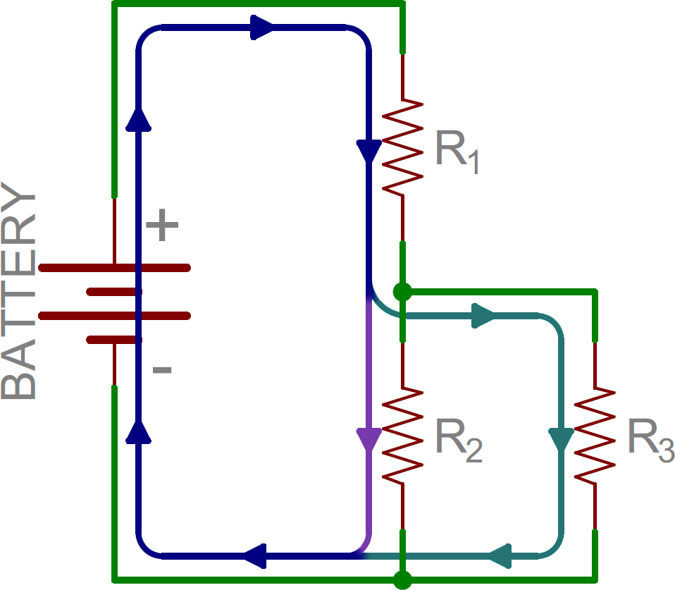
Web draw the circuit diagram for the circuit, being sure to draw an arrow indicating the direction of the current. Then she will have you try to draw. Bodechon will teach you the basic symbols used to draw electrical circuits. What does a series circuit look like? The schematic drawing is a better way to draw a series circuit.
Web Series Circuits Are Simpler And Have Their Unique Characteristics And Applications, Which We’ll Explore In More Detail.
Resistors are in series if the same current must pass sequentially through them. Web what is a series circuit? A circuit in series only has one loop that can be. Circuit symbols and circuit diagrams.
When We Talk About Visualizing A Series Circuit, Think Of.
To compare the values of current and electric potential at various locations within a series circuit and to explain the principles that form the basis of such comparisons. Web a series circuit is the most simple type of electrical circuit in which components (i.e. Now pick three spots along the wire. Use the appropriate list of major features for series or parallel connections to solve for the unknowns.
The Schematic Drawing Is A Better Way To Draw A Series Circuit.
Diagram of a series circuit. We’ll then explore what happens in series and parallel circuits when In this video we will look at a series circuit. Without changing the settings, allow the simulation to run for 20 s while you count the number of electrons passing through that spot.
Parallel Resistors (Part 1) Parallel Resistors (Part 2) Parallel Resistors (Part 3) Parallel Conductance.
Calculate the total circuit impedance, the circuits current, power factor and draw the voltage phasor diagram. As mentioned in the previous section of lesson 4, two or more electrical devices in a circuit can be connected by series connections or by parallel connections. Typically, complex circuits are not arranged in nice, neat, clean schematic diagrams for us to follow. Take a look at the diagram below: