Ductwork Drawings
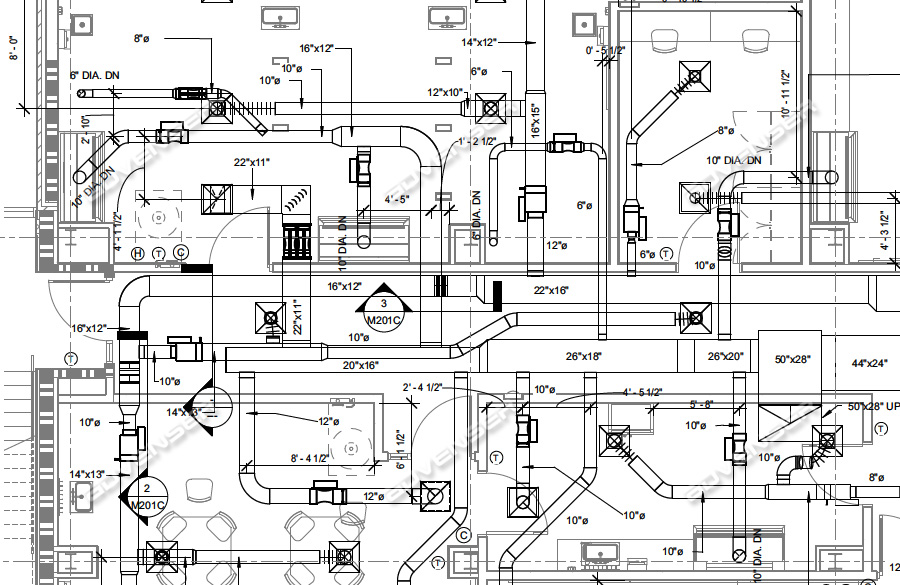
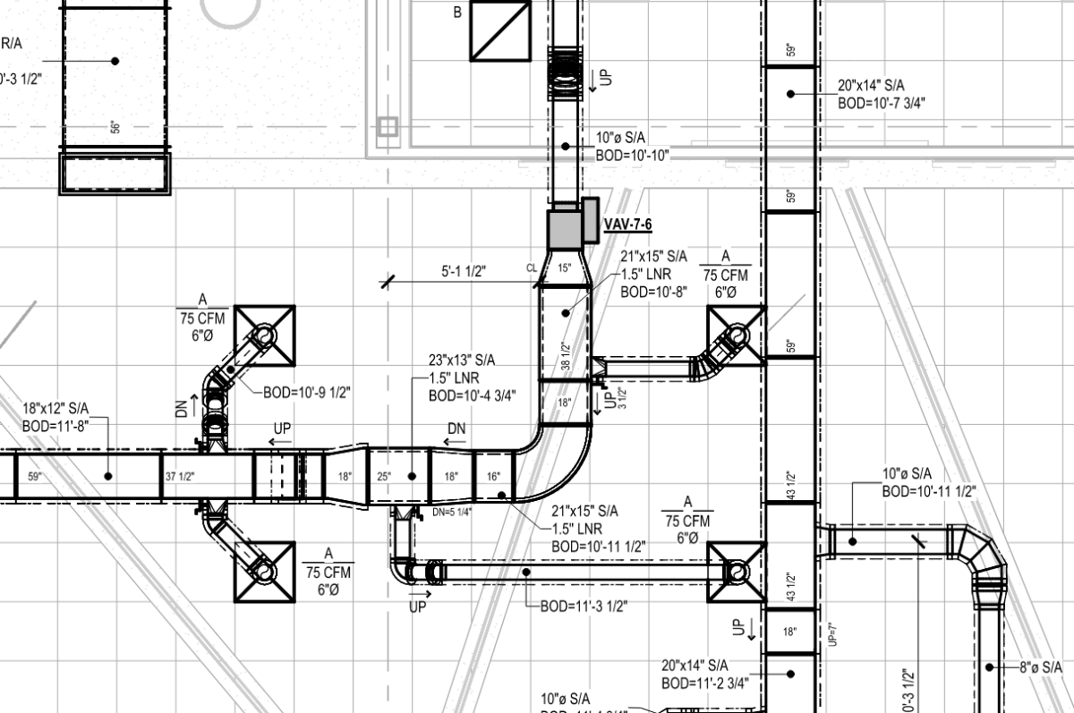
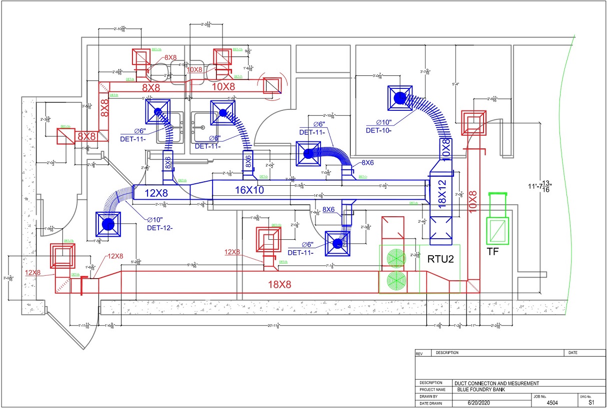
Ductwork Drawings - This hvac floor plan sample shows the ventilation duct system layout. So, how do you read hvac duct drawings? The hvac drawings include equipment and diffusers, which are provided in symbols on the drawings. An “x” in a square or round shape is indicative of supply air, while a single diagonal line indicates return air. This equipment needs to be described as it is used to estimate, order, and install at the site. Web an hvac duct shop drawings provided to a mechanical contractor or fabricator contain detailed information on how the duct has to be routed, along with the location of placement of duct accessories like duct fire dampers, volume control dampers, vav box etc. Solid lines represent walls, while dashed lines indicate openings. When it comes to shop drawings, there’s no substitute for experience and a proven track record. However, by understanding a few key symbols and features, you can learn how to read them like a pro! Web duct shop drawings are detailed schematics created by sheet metal fabricators to provide specific dimensions and specifications for the ductwork in hvac (heating, ventilation, and air conditioning) systems.
Bimoffis takes pride in upholding the highest industry standards to ensure successful hvac duct shop drawing. However, by understanding a few key symbols and features, you can learn how to read them like a pro! Well, the duct design software helps you to create a complete duct system from start to finish. How to get them right for maximum efficiency. Adherence to industrial standards and codes. This hvac floor plan sample shows the ventilation duct system layout. Web accurate hvac drawings facilitate the exact placement of hvac equipment, airflow management, and ductwork to create functional, practical, and comfortable indoor living conditions. They serve as a roadmap for the fabrication, installation, and coordination of ductwork within a building. To read hvac duct drawings, start by identifying the hvac equipment location and details. Check out our free hvac courses & certifications:
The information shares the points and marks with the size and fixation of the materials required with proper ventilation and environmental details. They are very important for hvac engineers. The first step is to identify the different types of lines on the drawing. They serve as a roadmap for the fabrication, installation, and coordination of ductwork within a building. Essentially, ductwork shop drawings are blueprints for your ductwork. The three most common being supply, return and exhaust. They help the involved parties to make sure that their systems do not collide or clash with each other enabling better and more efficient collaboration amongst. Web the following are used often throughout the mechanical drawings to indicate which type of air is in the ductwork, or which type of air distribution is being referenced. Web duct drawings are hvac drawings that shows the layout of ducted air conditioning systems and mechanical ventilation systems. Ducts are used in heating, ventilation, and air conditioning (hvac) to deliver and remove air.

A complete guide to HVAC drawings and blueprints
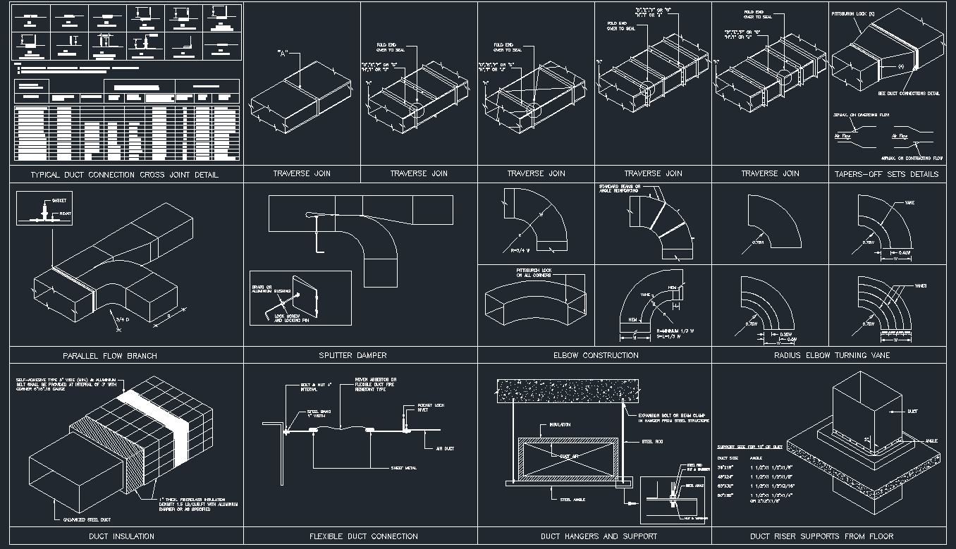
Essentially, ductwork shop drawings are blueprints for your ductwork. But what are they, exactly? They are very important for hvac engineers. When it comes to shop drawings, there’s no substitute for experience and a proven track record. Web free dwg drawings for cad blocks, symbols and details for duct work in hvac projects.
Hvac Drawing at GetDrawings Free download
Comfortable temperatures, good air quality and energy efficiency are just a few of the benefits occupants receive when your duct shop drawings are done right. Web hvac duct shop drawings offered by mars bim provides detailed understanding and information to the installers about the fixation of the ducts and equipments in the building structure. Hvac dynamic blocks for autocad and.
Duct detail cad drawing is given in this cad file. Download this cad
Check out our free hvac courses & certifications: Essentially, ductwork shop drawings are blueprints for your ductwork. They serve as a roadmap for the fabrication, installation, and coordination of ductwork within a building. In the world of hvac, ductwork shop drawings are essential. The drawings provide information on how the duct has to be routed, and the location of duct.

How to Read HVAC Duct Drawings? aircondlounge
Ducts are used in heating, ventilation, and air conditioning (hvac) to deliver and remove air. However, by understanding a few key symbols and features, you can learn how to read them like a pro! Web hvac duct shop drawings offered by mars bim provides detailed understanding and information to the installers about the fixation of the ducts and equipments in.
HVAC Duct Shop Drawings Ductwork Layout Drawings Advenser
Web learn about duct drawing symbols in this chapter of air handling and distribution course. Web designing the ductwork system involves selecting the exact size ducts and examining the airflow within the system via multiple simulation iterations for adequate conditions. Web accurate hvac drawings facilitate the exact placement of hvac equipment, airflow management, and ductwork to create functional, practical, and.
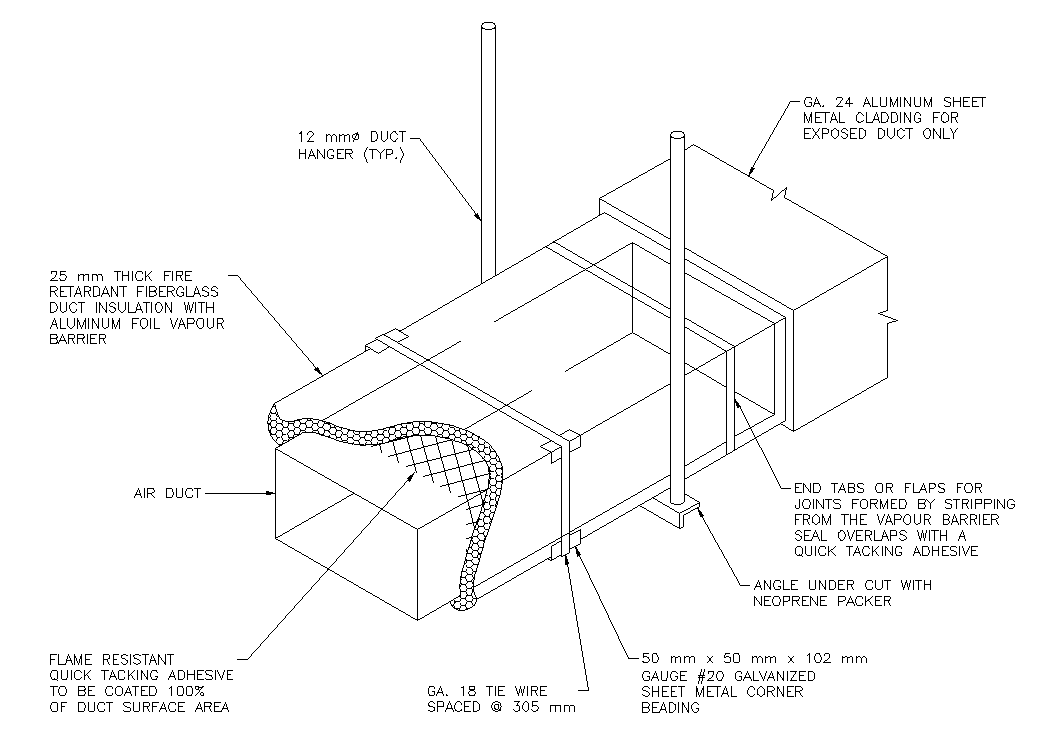
HVAC Ducting Details CAD Files, DWG files, Plans and Details
Web hvac duct shop drawings offered by mars bim provides detailed understanding and information to the installers about the fixation of the ducts and equipments in the building structure. Ducts are used in heating, ventilation, and air conditioning (hvac) to deliver and remove air. However, by understanding a few key symbols and features, you can learn how to read them.
HVAC Duct Fabrication drawings Revit MEP AutoCAD Forums
Web hvac duct shop drawings play a crucial role in the successful implementation of its systems. They are very important for hvac engineers. Also, it gives control over every aspect of the design. However, by understanding a few key symbols and features, you can learn how to read them like a pro! Web hvac duct shop drawings play a crucial.
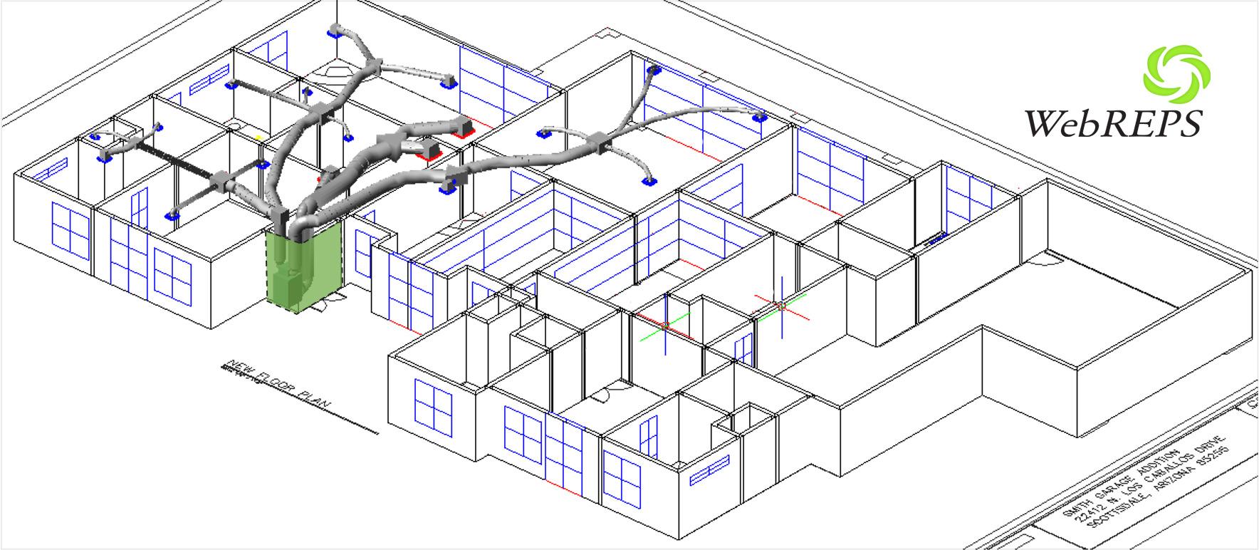
HVAC Ductwork Design Guide (Layout, Duct Size CFM) Aircondlounge vlr
Web hvac duct shop drawings play a crucial role in the successful implementation of its systems. This equipment needs to be described as it is used to estimate, order, and install at the site. At tcg, we start with that foundation and add irresistible advantages. Also, it gives control over every aspect of the design. Check out our free hvac.
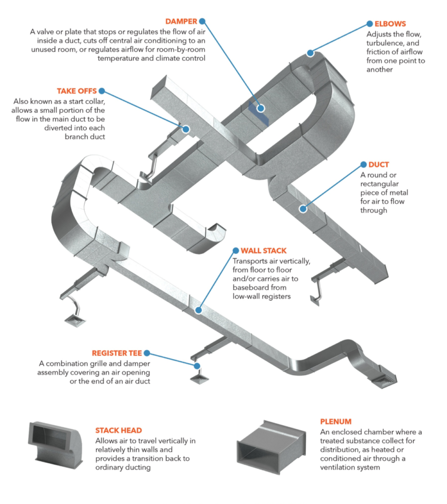
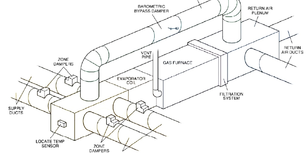
Ductwork Components Trade Air Australia
Web an hvac duct shop drawings provided to a mechanical contractor or fabricator contain detailed information on how the duct has to be routed, along with the location of placement of duct accessories like duct fire dampers, volume control dampers, vav box etc. Web free dwg drawings for cad blocks, symbols and details for duct work in hvac projects. Ducting.
Manual D Ductwork Design Service A/C Duct Design Calculation Services
Comfortable temperatures, good air quality and energy efficiency are just a few of the benefits occupants receive when your duct shop drawings are done right. What are ductwork shop drawings? This equipment needs to be described as it is used to estimate, order, and install at the site. Web free dwg drawings for cad blocks, symbols and details for duct.
This Equipment Needs To Be Described As It Is Used To Estimate, Order, And Install At The Site.
Web hvac duct drawings can be confusing for the layperson to read. Web duct drawings are hvac drawings that shows the layout of ducted air conditioning systems and mechanical ventilation systems. They help the involved parties to make sure that their systems do not collide or clash with each other enabling better and more efficient collaboration amongst. Web learn about duct drawing symbols in this chapter of air handling and distribution course.
An “X” In A Square Or Round Shape Is Indicative Of Supply Air, While A Single Diagonal Line Indicates Return Air.
They show the layout and design of your ductwork and all the necessary dimensions. This hvac floor plan sample shows the ventilation duct system layout. Web accurate hvac drawings facilitate the exact placement of hvac equipment, airflow management, and ductwork to create functional, practical, and comfortable indoor living conditions. Our hvac duct shop drawing services encompass a wide range of offerings, including hvac shop drawings, duct design services, duct fabrication drawings, and more.
Web Hvac Duct Shop Drawings Play A Crucial Role In The Successful Implementation Of Its Systems.
But what are they, exactly? Web hvac duct shop drawings offered by mars bim provides detailed understanding and information to the installers about the fixation of the ducts and equipments in the building structure. Check out our free hvac courses & certifications: The needed airflows include, for example, supply air, return air, and exhaust air.
So, How Do You Read Hvac Duct Drawings?
Free download now the mepwork collection of hvac blocks for hvac design engineers. Also, it gives control over every aspect of the design. The three most common being supply, return and exhaust. Hvac shop drawings are detailed technical drawings providing an extensive depiction of hvac systems within a building.