Electrical Engineering Drawings
Electrical Engineering Drawings - System level function blocks, physical 3d models and prints, piping and instrument diagrams (p&ids), wiring diagrams, ladder diagrams, electrical power flow diagrams, pcb schematics… you get the idea. You will become familiar with the many types of diagrams and how to distinguish between them, as well as how to choose the appropriate diagram for a given situation and how to comprehend a logic sequence and a combinatory sequence. Familiarize with standardized electrical symbols. Web learn about autodesk electrical drawing software for engineering or architecture. Web there are four basic types of electrical diagrams: Web understanding electrical drawings is super important in the world of electrical engineering and design. Select one of the following: Web electrical drawings and schematics. Web among these you'll find commonly used electrical drawings and schematics, like circuit diagrams, wiring diagrams, electrical plans and block diagrams. On the file tab, select new, and then search for engineering templates.
Web welcome to this comprehensive technical article that delves into the intricacies of electrical schematics, shedding light on crucial elements such as loops, wire connections, auxiliary contacts, mcbs, contactors, circuit breakers, isolators, earth switches, and terminal blocks. The purpose of this guide is to give you the basics of engineering sketching and drawing. Web there are four basic types of electrical diagrams: One of the best ways to communicate one’s ideas is through some form of picture or drawing. Create engineering diagrams such as electrical diagrams, circuit and logic diagrams, industrial control systems, process flow, p&id and systems diagrams. “sketching” generally means freehand drawing. Web the electrical drawings consist of electrical outlets, fixtures, switches, lighting, fans, and appliances. Web electrical engineering symbology, prints and drawings. Web use the electrical engineering drawing type in visio professional or visio plan 2 to create electrical and electronic schematic diagrams. Web electrical drawings, also called electrical plans or wiring diagrams, are a kind of technical drawing that provides visual representations of circuits or electrical systems.
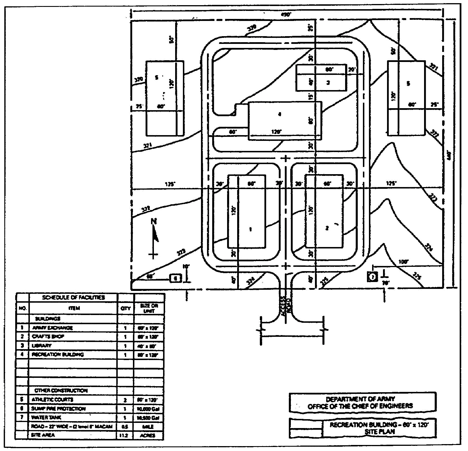
Start with a circuit diagram template. Web the engineering world is crammed full of drawings and diagrams of every possible kind. One of the key tools in developing and documenting an electrical power system is the single line diagram (shortened sld). Web in electrical and electronics engineering, we use different types of drawings or diagrams to represent a certain electrical system or circuit. Web electrical engineering symbology, prints and drawings. These drawings are like a special language that helps us turn ideas into real electrical systems. Web a practical handbook for reading and analysing electrical drawings and diagrams. Knowing the meanings of basic electrical symbols in your electrical drawing will help you quickly understand and troubleshooting the circuit. Schedules help to find the details of the equipment or fixtures used on the plans. Get started with free tools, resources, and tutorials.

Electrical Engineering Drawings Close Up Stock Image Image of
Schedules help to find the details of the equipment or fixtures used on the plans. Enabling objectives 1.1 identify the symbols used on engineering electrical drawings for the following components: Web an electrical drawing is a type of technical drawing that shows information about power, lighting, and communication for an engineering or architectural project. “sketching” generally means freehand drawing. These.

ARCXEN CAD Design Studio Electrical Engineering Drawings
This book was developed by idc technologies. One of the best ways to communicate one’s ideas is through some form of picture or drawing. Web schematic drawings, also known as electrical or circuit diagrams, are essential tools for understanding and designing electrical circuits. Usually represented as a circle with a cross inside it. General notes, abbreviations, legends, and symbols, are.

Electrical Engineering Drawings Close Up Stock Photo Image of plan
One of the key tools in developing and documenting an electrical power system is the single line diagram (shortened sld). Web among these you'll find commonly used electrical drawings and schematics, like circuit diagrams, wiring diagrams, electrical plans and block diagrams. Web electrical drawings and schematics. Web the electrical drawings consist of electrical outlets, fixtures, switches, lighting, fans, and appliances..

Electrical Engineering Drawings and Pencils Stock Image Image of
Start with a circuit diagram template. Web electrical drawings and schematics. Web among these you'll find commonly used electrical drawings and schematics, like circuit diagrams, wiring diagrams, electrical plans and block diagrams. This is especially true for the engineer. Web a practical handbook for reading and analysing electrical drawings and diagrams.

Paper Electrical Engineering Drawings with Circuit Breaker and
Usually represented as a circle with a cross inside it. One of the key tools in developing and documenting an electrical power system is the single line diagram (shortened sld). These electrical circuits are represented by lines to represent wires and symbols or icons to. Web the engineering world is crammed full of drawings and diagrams of every possible kind..

Electrical Engineering Drawings and Pencils Stock Photo Image of plan
Mastering schematic drawing is a fundamental skill for field engineers, allowing them to effectively troubleshoot, maintain, and modify electrical schemes. Web what is the single line diagram? Web 1.0 given an electrical print, read and interpret facility electrical diagrams and schematics. The purpose of this guide is to give you the basics of engineering sketching and drawing. Web welcome to.

ARCXEN CAD Design Studio Electrical Engineering Drawings
Web in electrical and electronics engineering, we use different types of drawings or diagrams to represent a certain electrical system or circuit. Web electrical drawings, also called electrical plans or wiring diagrams, are a kind of technical drawing that provides visual representations of circuits or electrical systems. They are sort of like a layout on paper prior to physically installing.
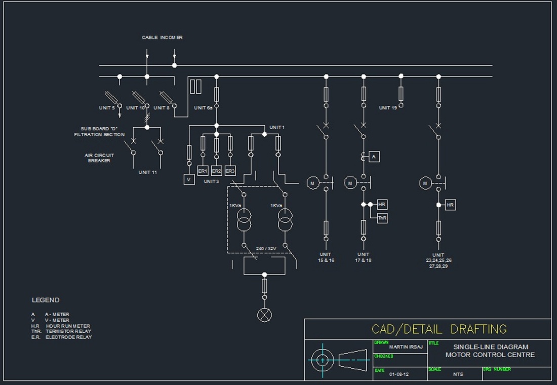
Sample of Electrical Drawings Martin Irsaj
These electrical circuits are represented by lines to represent wires and symbols or icons to. Web a practical handbook for reading and analysing electrical drawings and diagrams. This is especially true for the engineer. The handbook includes information on engineering fluid drawings and prints; Web make circuit diagrams, wiring diagrams, electrical drawing, schematics, and more with smartdraw.

Paper Electrical Engineering Drawings with Circuit Breaker and
Create engineering diagrams such as electrical diagrams, circuit and logic diagrams, industrial control systems, process flow, p&id and systems diagrams. Web welcome to this comprehensive technical article that delves into the intricacies of electrical schematics, shedding light on crucial elements such as loops, wire connections, auxiliary contacts, mcbs, contactors, circuit breakers, isolators, earth switches, and terminal blocks. Select one of.
Electrical Engineer Drawing at GetDrawings Free download
First of all, power system designers should always communicate their design requirements through a combination of drawings, schedules and technical specifications. How to read a electrical drawing. Web among these you'll find commonly used electrical drawings and schematics, like circuit diagrams, wiring diagrams, electrical plans and block diagrams. Web make circuit diagrams, wiring diagrams, electrical drawing, schematics, and more with.
“Sketching” Generally Means Freehand Drawing.
The purpose of this guide is to give you the basics of engineering sketching and drawing. Web an electrical drawing is a type of technical drawing that shows information about power, lighting, and communication for an engineering or architectural project. Idc technologies is internationally acknowledged as the premier provider of practical, technical training for engineers and technicians. Web schematic drawings, also known as electrical or circuit diagrams, are essential tools for understanding and designing electrical circuits.
Web Make Circuit Diagrams, Wiring Diagrams, Electrical Drawing, Schematics, And More With Smartdraw.
Web there are four basic types of electrical diagrams: They are sort of like a layout on paper prior to physically installing the required machines. Web welcome to this comprehensive technical article that delves into the intricacies of electrical schematics, shedding light on crucial elements such as loops, wire connections, auxiliary contacts, mcbs, contactors, circuit breakers, isolators, earth switches, and terminal blocks. One of the key tools in developing and documenting an electrical power system is the single line diagram (shortened sld).
Web Use The Electrical Engineering Drawing Type In Visio Professional Or Visio Plan 2 To Create Electrical And Electronic Schematic Diagrams.
Enabling objectives 1.1 identify the symbols used on engineering electrical drawings for the following components: Web learn about autodesk electrical drawing software for engineering or architecture. Web a practical handbook for reading and analysing electrical drawings and diagrams. Web understanding electrical drawings is super important in the world of electrical engineering and design.
Web The Electrical Drawings Consist Of Electrical Outlets, Fixtures, Switches, Lighting, Fans, And Appliances.
The handbook includes information on engineering fluid drawings and prints; First of all, power system designers should always communicate their design requirements through a combination of drawings, schedules and technical specifications. General notes, abbreviations, legends, and symbols, are found on the first page of the electrical drawings. System level function blocks, physical 3d models and prints, piping and instrument diagrams (p&ids), wiring diagrams, ladder diagrams, electrical power flow diagrams, pcb schematics… you get the idea.