Electrical Single Line Drawing
Electrical Single Line Drawing - In this post you’ll learn what is single line diagram and why do we need it. How is a single line diagram calculated? “a diagram which shows, by means of single lines and graphic symbols, the course of an electric circuit or system of circuits and the component devices or parts used therein.” Web what is a single line diagram? They are used to represent and communicate the structure and connections within an electrical system in a simplified and standardized manner. A circuit diagram allows you to visualize how components of a circuit are laid out. Web by r jagan mohan rao. In this post, i will show why you need an sld and how to make it. Ladder diagram or line diagram. A single line diagram is method of simplified representation of a three phase power system.
It is a simplified drawing of the whole system or a portion of the power system that shows the electrical placement of all major equipment. The diagram is commonly used in designing, operating, and maintaining electrical power systems. A single line can show all or part of a system. It will have one single line shown for bus (or cable) to represent all three phases. Single line diagrams are used in common engineering practice as graphical representation of electrical switchboard or assembly containing more sections, i.e. It is used by electricians, engineers, and technicians to understand the electrical components and connections within a system. Electrical single line and schematic symbols 0.00 kb 692 downloads. This condenses the space and complexity of the diagram for simpler troubleshooting. Web what is a single line diagram? A single line in the diagram typically corresponds to more than one physical conductor:
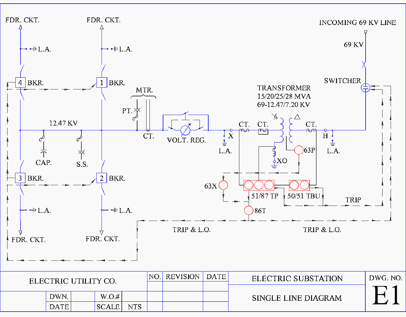
In this video, i'll explain how to read substation single line diagram (sld) in 5 simple steps. It uses standardized symbols to depict various elements such as generators, transformers, switches, motors, and protective devices. Web this electrical one line diagram is the primary reference for maintenance and operations for lockout/tagout procedures, as well as for any engineering power system studies. Lines connect fuses, switches, capacitors, inductors, and. Web an electrical single line diagram is a graphical representation of an electrical system’s components and connections. It is the first step in preparing a critical response plan, allowing you to become thoroughly familiar with the electrical distribution system layout and design in your facility. Transmission, distribution, and power transformers are also three phases. It is used by electricians, engineers, and technicians to understand the electrical components and connections within a system. Web what is a single line diagram? A circuit diagram allows you to visualize how components of a circuit are laid out.
Electrical Single Line Diagram Part Two Electrical Knowhow
Single line diagrams are used in common engineering practice as graphical representation of electrical switchboard or assembly containing more sections, i.e. Web an electrical single line diagram is a graphical representation of an electrical system’s components and connections. In this post you’ll learn what is single line diagram and why do we need it. Lines connect fuses, switches, capacitors, inductors,.
Electrical Single Line Diagram Template (DWG) — LINE DRAW CAD LAB
Ladder diagram or line diagram. “a diagram which shows, by means of single lines and graphic symbols, the course of an electric circuit or system of circuits and the component devices or parts used therein.” Web an electrical single line diagram is a graphical representation of an electrical system’s components and connections. A single line diagram is method of simplified.
how to prepare electrical single line diagram Wiring Diagram and
Transmission, distribution, and power transformers are also three phases. Web we usually depict the electrical distribution system by a graphic representation called a single line diagram (sld). How is a single line diagram calculated? It is used by electricians, engineers, and technicians to understand the electrical components and connections within a system. A single line in the diagram typically corresponds.
how to prepare electrical single line diagram Wiring Diagram and
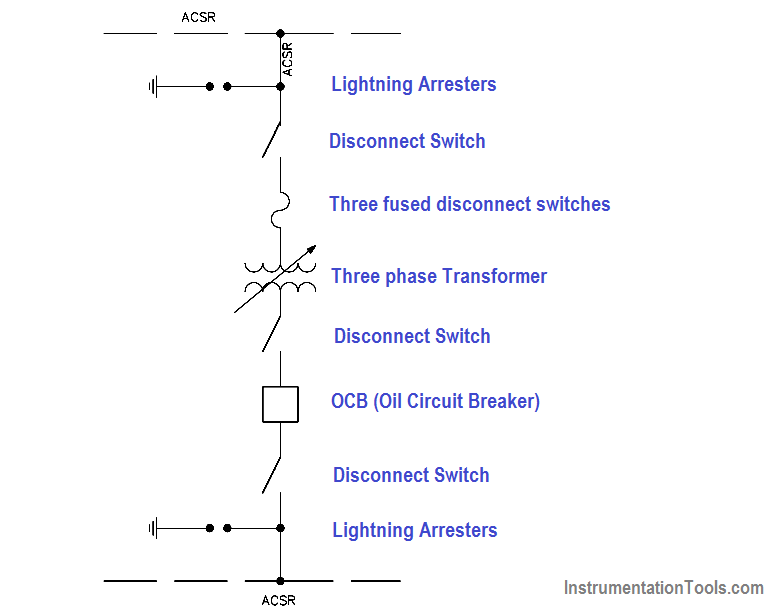
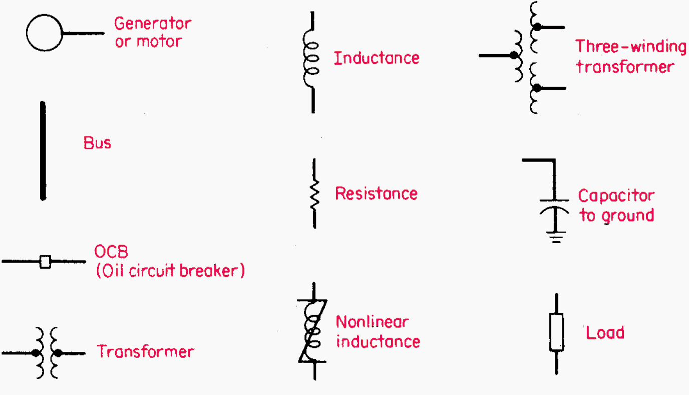
For electric power networks an appropriate selection of graphic symbols is shown in figure 1 (common power symbols used in single line diagrams): The easy choice for creating your circuit drawing online. A single line diagram is method of simplified representation of a three phase power system. How is a single line diagram calculated? It is the first step in.
Understanding Substation Single Line Diagrams and IEC 61850 Process Bus
It is used by electricians, engineers, and technicians to understand the electrical components and connections within a system. Ladder diagram or line diagram. Web we usually depict the electrical distribution system by a graphic representation called a single line diagram (sld). Web draw your circuit diagram. A single line can show all or part of a system.
How To Calculate and Draw a Single Line Diagram For The Power System EEP
The easy choice for creating your circuit drawing online. It is a simplified drawing of the whole system or a portion of the power system that shows the electrical placement of all major equipment. The best online circuit diagram maker. Transmission, distribution, and power transformers are also three phases. A circuit diagram allows you to visualize how components of a.

Single Line Diagram of Power Plant Power Systems
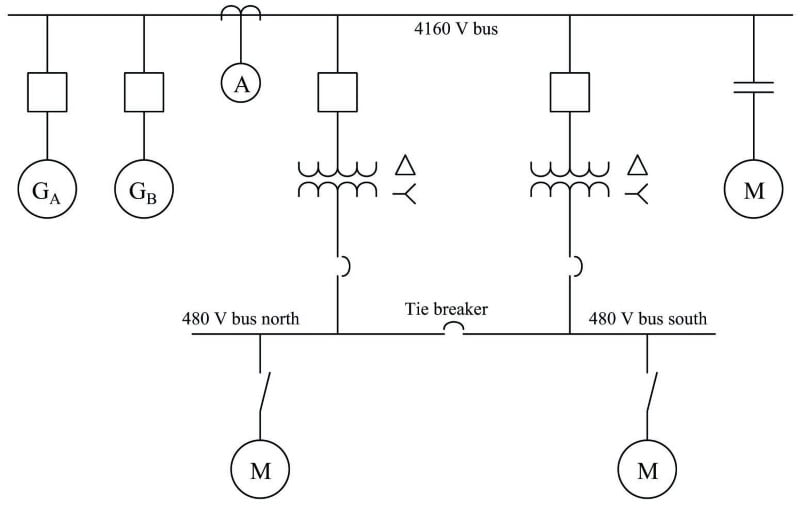
It will have one single line shown for bus (or cable) to represent all three phases. A single line diagram is method of simplified representation of a three phase power system. Web we usually depict the electrical distribution system by a graphic representation called a single line diagram (sld). It uses standardized symbols to depict various elements such as generators,.

How to Read and Understand an Electrical Single Line Diagram?
Symbols and lines are used to represent the nodes and connections in the system, and electrical characteristics may be included as well. It is used by electricians, engineers, and technicians to understand the electrical components and connections within a system. It will have one single line shown for bus (or cable) to represent all three phases. Three phases are denoted.
Electrical SingleLine Diagram Intelligent One Line Diagram ETAP
Web we usually depict the electrical distribution system by a graphic representation called a single line diagram (sld). Web an electrical single line diagram is a graphical representation of an electrical system’s components and connections. Transmission, distribution, and power transformers are also three phases. A single line diagram is method of simplified representation of a three phase power system. “a.
Singleline Electrical Diagrams Electric Power Measurement and
Web draw your circuit diagram. It will have one single line shown for bus (or cable) to represent all three phases. Symbols and lines are used to represent the nodes and connections in the system, and electrical characteristics may be included as well. Web an electrical single line diagram is a graphical representation of an electrical system’s components and connections..
It Shows The Flow Of Electricity Through The System Using A Single Line And Standardized Electrical Symbols.
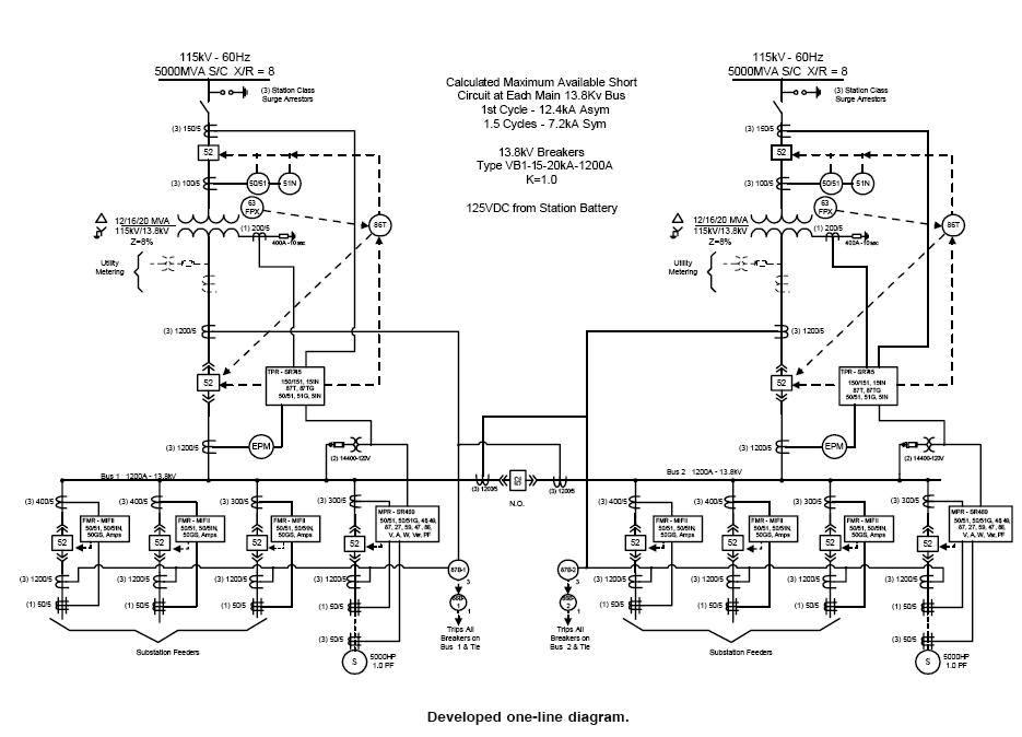
In this post, i will show why you need an sld and how to make it. Three phases are denoted by a single conductor i.e., power system is assumed in a balanced steady state. It will have one single line shown for bus (or cable) to represent all three phases. Web this electrical one line diagram is the primary reference for maintenance and operations for lockout/tagout procedures, as well as for any engineering power system studies.
Transmission, Distribution, And Power Transformers Are Also Three Phases.
Web draw your circuit diagram. Single line diagrams are used in common engineering practice as graphical representation of electrical switchboard or assembly containing more sections, i.e. Symbols and lines are used to represent the nodes and connections in the system, and electrical characteristics may be included as well. The best online circuit diagram maker.
It Uses Standardized Symbols To Depict Various Elements Such As Generators, Transformers, Switches, Motors, And Protective Devices.
In this video, i'll explain how to read substation single line diagram (sld) in 5 simple steps. Ladder diagram or line diagram. Web by r jagan mohan rao. How is a single line diagram calculated?
It Is Used By Electricians, Engineers, And Technicians To Understand The Electrical Components And Connections Within A System.
It is a simplified drawing of the whole system or a portion of the power system that shows the electrical placement of all major equipment. The easy choice for creating your circuit drawing online. They are used to represent and communicate the structure and connections within an electrical system in a simplified and standardized manner. “a diagram which shows, by means of single lines and graphic symbols, the course of an electric circuit or system of circuits and the component devices or parts used therein.”