Electrical Wiring Drawing Symbols
Electrical Wiring Drawing Symbols - Solidworks electrical schematic professional is a suite of collaborative schematic design tools that drive rapid development of embedded electrical systems. Web the most common resistor symbols include a zigzag line and a rectangle with a diagonal line. Web electrical drawing symbols are used in both wiring diagrams and wiring schematics. Navigate to building plan > eletrical and telecom plan. Before you can learn how to read a diagram, you must understand what. Represents a component that resists the flow of electrical current, often used to control the amount of current in a circuit.; Depicts electrical devices as drawings or pictures connected by lines representing wires. Web smartdraw lets you choose from an enormous library of professionally designed electrical symbols for block diagrams, circuit panels, wiring diagrams, and many other types of drawings. In lucidchart, there are four major types of relay symbols that are labeled. Launch edrawmax on your computer.
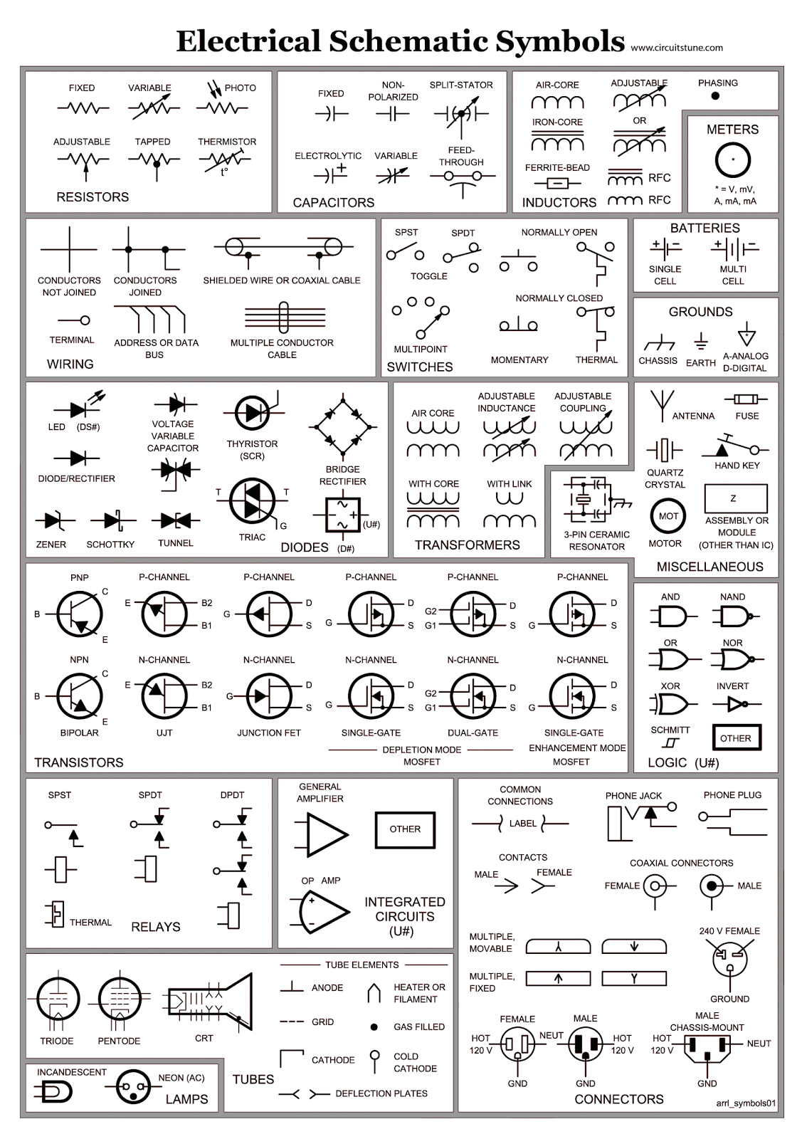
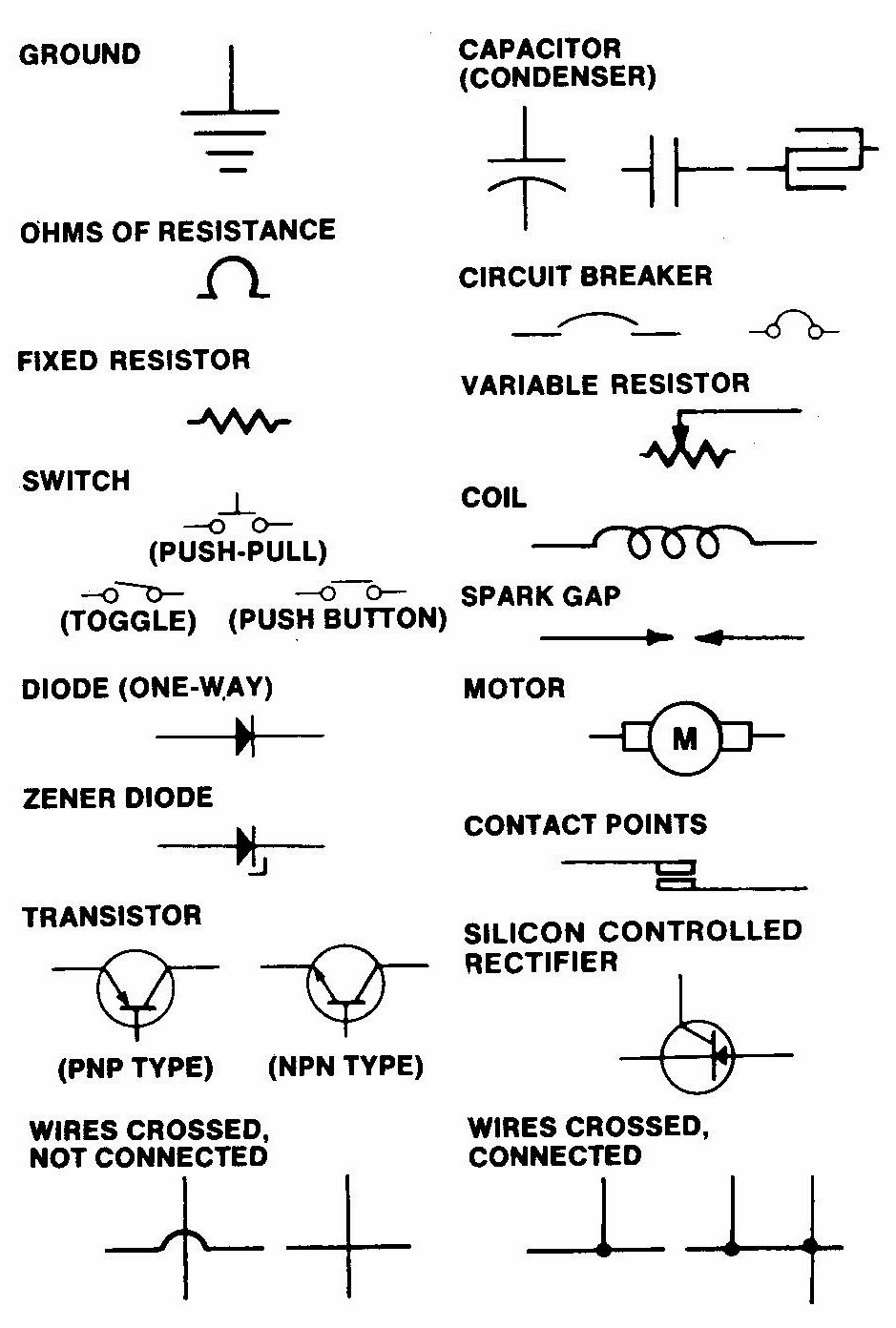
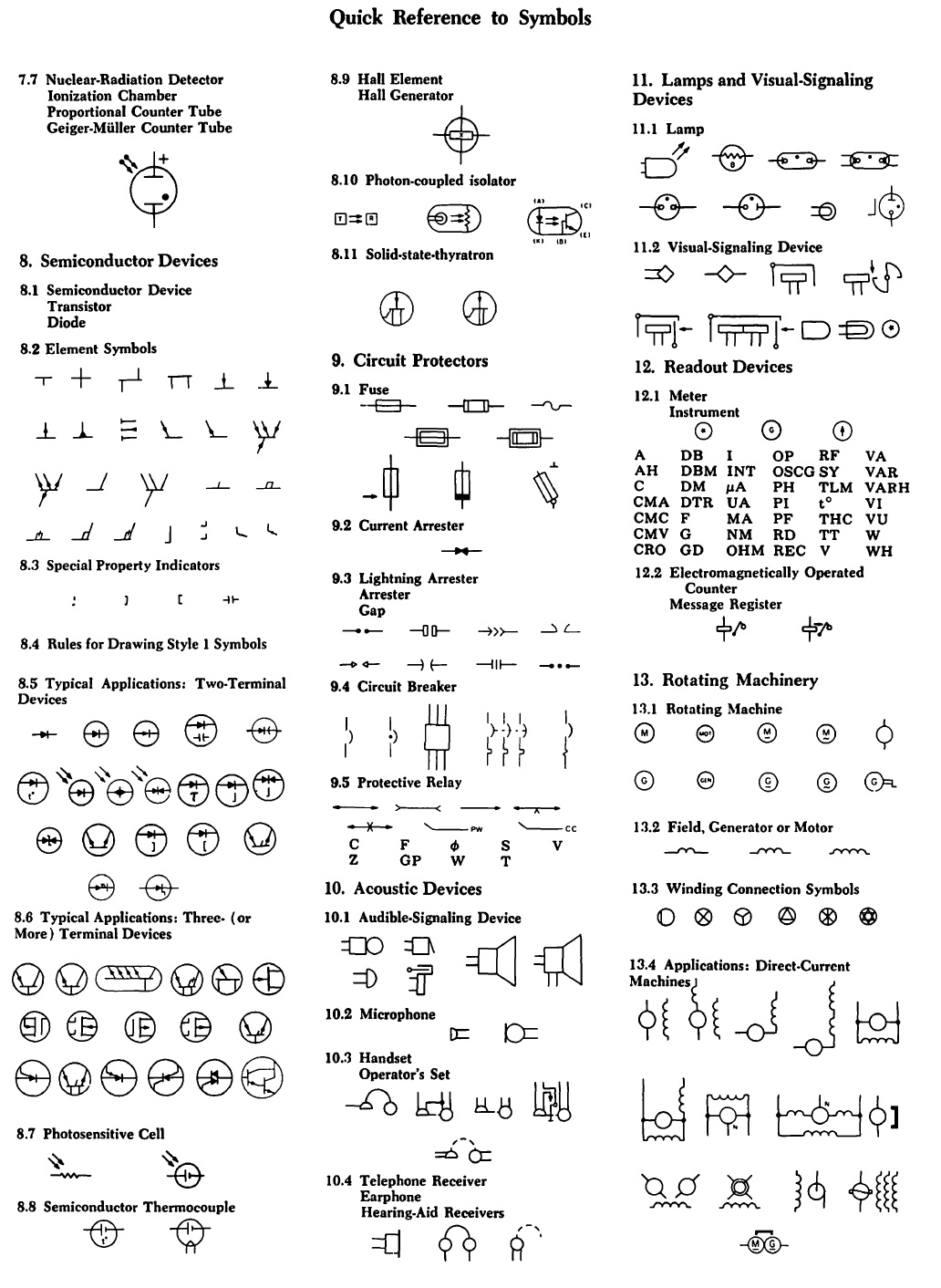
Web basic electrical and electronic graphical symbols called schematic symbols are commonly used within circuit diagrams, schematics and computer aided drawing packages to identify the position of individual components and elements within a circuit. Smartdraw is easy to use too. Web the most common resistor symbols include a zigzag line and a rectangle with a diagonal line. Customize hundreds of electrical symbols and quickly drop them into your wiring diagram. Lamp and light symbols are used to represent lighting elements in wiring diagrams. Wiring diagrams show the connections and physical layout of. Web it represents an electrical blueprint and drawing symbol. Within the scope of these drawings, the symbols that indicate each device are a mix of function blocks and schematics. Web electrical drawing symbols are used in both wiring diagrams and wiring schematics. As we can see in the image, the wiring provided to the light from the switchboard.
To draw a wire, simply click on the draw lines option on the left hand side of the drawing. As you enter into the workspace of edrawmax, you can drag and drop the symbols that you need onto the canvas. Web there are three basic types of wiring diagrams: Within the scope of these drawings, the symbols that indicate each device are a mix of function blocks and schematics. In lucidchart, there are four major types of relay symbols that are labeled. Depicts a device that can open or close a circuit, controlling the flow of electricity to a load.; We'll go over all of the fundamental schematic symbols: Open an wiring diagram example or a blank drawing page. Then we'll talk about how those symbols are connected on schematics to create a model of a circuit. An electronic symbol is a pictogram used to represent various electrical and electronic devices or functions, such as wires, batteries, resistors, and transistors, in a schematic diagram of an electrical or electronic circuit.
Electrical Symbols Electrical Drawing Symbols Electrical Academia
As we can see in the image, the wiring provided to the light from the switchboard. Web electrical drawing symbols are used in both wiring diagrams and wiring schematics. If you need additional symbols, search them on the left symbol library. Within the scope of these drawings, the symbols that indicate each device are a mix of function blocks and.

Electrical Wiring Circuit Symbols
This tutorial should turn you into a fully literate schematic reader! Solidworks electrical schematic professional is a suite of collaborative schematic design tools that drive rapid development of embedded electrical systems. Wiring diagrams show the connections and physical layout of. You can easily rotate a relay, or any other icon in lucidchart, to fit the parameters of your circuit diagram..
.jpg)
Basic Wiring Diagram Symbols
Click and stamp electrical symbols onto your layout. Isolator is a mechanical switch that isolates a part of a circuit from the system as when required. Shows how components are related to others on the same circuit, but contains less detailed information about electrical. Web solidworks electrical schematic professional. As we can see in the image, the wiring provided to.

Basic Electrical Wiring Diagram Symbols For Architecture Annabel Cole
Electrical schematics are used by electricians, engineers, and technicians to understand and troubleshoot. Web basic electrical and electronic graphical symbols called schematic symbols are commonly used within circuit diagrams, schematics and computer aided drawing packages to identify the position of individual components and elements within a circuit. Navigate to building plan > eletrical and telecom plan. These symbols indicate the.
Basic Electrical Wiring Diagram Symbols
These paths are inside the ceiling and can be seen in a wiring layout. Web there are three basic types of wiring diagrams: Web an electrical schematic is a diagram that shows how all of the wires and components in an electronic circuit are connected. These symbols indicate the presence of resistance in a circuit, which limits the flow of.
12v Wiring Diagram Symbols
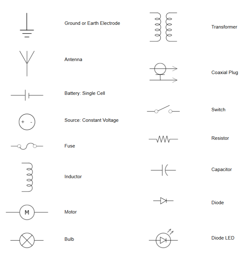
Web electrical symbols and electronic circuit symbols are used for drawing schematic diagram. Wiring diagram symbols represent various electrical and electronic components such as resistors, capacitors, diodes, switches, transformers, and more. The wiring layout consists of wiring routing is a set path for wires. Customize hundreds of electrical symbols and quickly drop them into your wiring diagram. Web an electrical.
How to Read and Interpret Electrical Shop Drawings Part Two
Web an electrical schematic, also known as a wiring diagram or circuit diagram, is a visual representation of an electrical circuit. Lamp and light symbols are used to represent lighting elements in wiring diagrams. Web basic electrical and electronic graphical symbols called schematic symbols are commonly used within circuit diagrams, schematics and computer aided drawing packages to identify the position.

Common Electrical Symbols Electrical symbols, Blueprint symbols, Dc
Web an electrical schematic, also known as a wiring diagram or circuit diagram, is a visual representation of an electrical circuit. In lucidchart, there are four major types of relay symbols that are labeled. Depicts a device that can open or close a circuit, controlling the flow of electricity to a load.; Each component is depicted by a unique symbol.
Electrical Symbols Try Our Electrical Symbol Software Free
Web there are three basic types of wiring diagrams: As you enter into the workspace of edrawmax, you can drag and drop the symbols that you need onto the canvas. Each symbol is designed to represent a specific electrical component or. In lucidchart, there are four major types of relay symbols that are labeled. Web the picture below shows switches.

Electrical wiring diagram switches symbols Electrical Industrial
The ability to read electrical schematics is a really useful skill to. Customize hundreds of electrical symbols and quickly drop them into your wiring diagram. Web electrical drawing symbols are used in both wiring diagrams and wiring schematics. Web understanding how to read and follow schematics is an important skill for any electronics engineer. Solidworks electrical schematic professional is a.
Chapter 2Basic Symbolsin This Module, We Will Introduce You To Some Of The Basic Symbols You Will Find On A Wiring Diagram.
These symbols indicate the presence of resistance in a circuit, which limits the flow of electrical current. Each component is depicted by a unique symbol that is easily identifiable. Navigate to building plan > eletrical and telecom plan. Wiring diagram symbols also indicate how components are connected within a circuit.
Web An Electrical Schematic Is A Diagram That Shows How All Of The Wires And Components In An Electronic Circuit Are Connected.
In lucidchart, there are four major types of relay symbols that are labeled. Web wiring schematic symbols are important because they provide a standardized way to represent different components and connections in a wiring diagram. These categories include power supplies, switches, relays, conductors, capacitors, resistors, transformers, motors, and more. This makes it easier for engineers, technicians, and electricians to read and understand the diagrams, which in turn helps them to design, build, and troubleshoot electrical systems more effectively.
Web Electrical Wiring Diagram Symbols Are Typically Classified Into Several Categories Based On The Type Of Component Or Connection They Represent.
Electrical diagrams and schematics visually represent electrical circuits in different ways. These symbols are largely standardized internationally today, but may vary from country to country. As you enter into the workspace of edrawmax, you can drag and drop the symbols that you need onto the canvas. Web the most common resistor symbols include a zigzag line and a rectangle with a diagonal line.
Launch Edrawmax On Your Computer.
We'll also go over a. Wiring diagram symbols represent various electrical and electronic components such as resistors, capacitors, diodes, switches, transformers, and more. We'll go over all of the fundamental schematic symbols: As we can see in the image, the wiring provided to the light from the switchboard.