Engineering Drawing Dimensioning
Engineering Drawing Dimensioning - All of these building blocks are equally important for defining the drawing clearly and unambiguously. Web learn how geometric dimensioning and tolerancing is used in the real world, not just in theory, with training tailored to provide practical engineering solutions. Web essentially, dimensioning refers to the process of specifying the exact size, shape, and location of different parts and features on an engineering drawing. In this article, we are going to talk about dimensions. The dimension line is a fine, dark, solid line with arrowheads on each end. Web the purpose of dimensioning is to provide a clear and complete description of an object. Our comprehensive guide covers techniques, standards, and best practices for accuracy and clarity. In introduction to the engineering drawings, we showed you the building blocks of the engineering drawing. The purpose of engineering drawings is to convey objective facts, whereas artistic drawings convey emotion or artistic sensitivity in some way. Web standards are formally published documents that establish consistent technical requirements for products, practices, methods, or operations, thereby ensuring uniformity, quality, and safety.
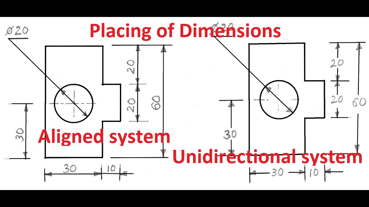
Dimensions must be placed in appropriate positions. The arrow and leader should be placed to avoid clutter and overlaps. Applications in civil, architectural, and engineering design. Web in this video, we are going to learn about dimensions in engineering drawing! The purpose of engineering drawings is to convey objective facts, whereas artistic drawings convey emotion or artistic sensitivity in some way. A circular arc is dimensioned by its radius using the symbol “r”. Web the process of adding size information to a drawing is known as dimensioning the drawing. A complete set of dimensions will permit only one interpretation needed to construct the part. Engineering drawings and sketches need to display simplicity and. Web three principles of dimensioning must be followed:
In machine sketches and drawings, in which fractions and decimals are used for dimensions, the dimension line is usually broken near the middle to provide open space for the dimension numerals. We are going to look at what dimensioning is, what are the elements of the dimensions and what the rules for. Web what is dimensioning in engineering drawing? A circular arc is dimensioned by its radius using the symbol “r”. Explore design formats, practices, rules, requirements, terms, definitions and more across drawings & models. All of these building blocks are equally important for defining the drawing clearly and unambiguously. To construct an object its shape and size must be known. To avoid confusion and the possibility of error, no dimension should be repeated twice on any sketch or drawing. Asme y14.37 2019 product definition for composite parts standard. Web the process of adding size information to a drawing is known as dimensioning the drawing.
Dimensioning Basic Blueprint Reading
Web three principles of dimensioning must be followed: A circular arc is dimensioned by its radius using the symbol “r”. Engineering drawings fundamentals introduces the fundamental concepts that are required to read, understand, and interpret engineering drawings used throughout the manufacturing industry. Web geometric dimensioning and tolerancing is a set of rules and gd&t symbols used on a drawing to.

Types Of Dimensions In Engineering Drawing at GetDrawings Free download
Web learn everything you need to know about dimensioning engineering drawings. A circular arc is dimensioned by its radius using the symbol “r”. Applications in civil, architectural, and engineering design. Web the new ipad pro — the thinnest apple product ever — features a stunningly thin and light design, taking portability to a whole new level. It indicates direction and.

Lecture Notes Engineering Drawing Part 4
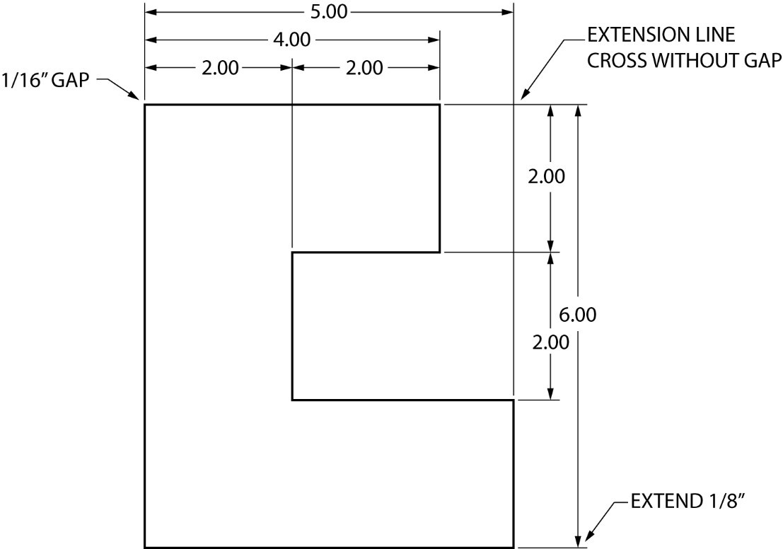
Once the shape of a part is defined with an orthographic drawings, the size information is added also in the form of dimensions. The dimension line is a fine, dark, solid line with arrowheads on each end. Web in other words, indicating on a drawing, the sizes of the object and the other details essential for its construction and function.
Dimensioning and sectioning in engineering drawing. Engineering Drawing
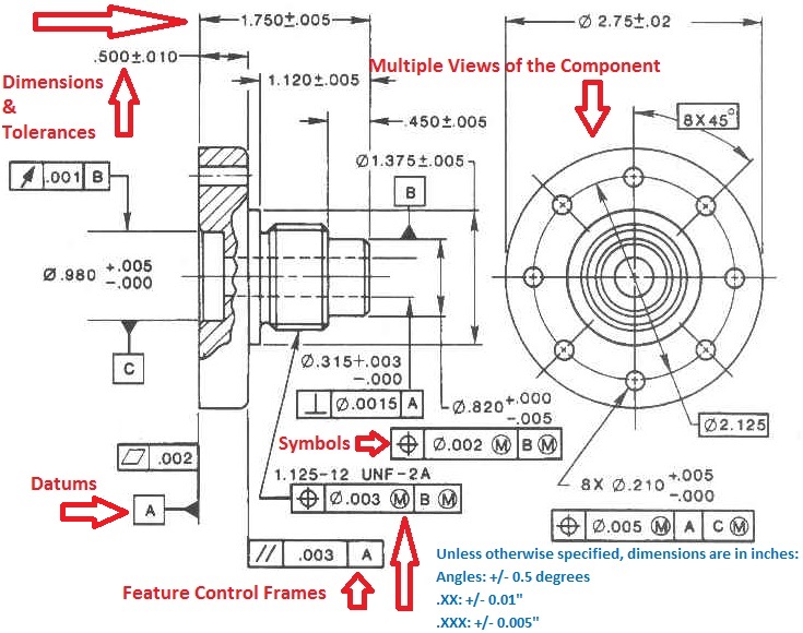
Engineering drawings fundamentals introduces the fundamental concepts that are required to read, understand, and interpret engineering drawings used throughout the manufacturing industry. Web the purpose of dimensioning is to provide a clear and complete description of an object. Using gd&t results in a more accurate design, larger tolerances for less important design features, and cost savings for manufacturing. The arrow.

Types Of Dimensions In Engineering Drawing at GetDrawings Free download
Web learn the fundamental rules of dimensioning in engineering/architectural/structural drawings. Web three principles of dimensioning must be followed: Once the shape of a part is defined with an orthographic drawings, the size information is added also in the form of dimensions. Engineering drawings and sketches need to display simplicity and. Web standards are formally published documents that establish consistent technical.

Types Of Dimensions In Engineering Drawing at GetDrawings Free download
Benefits of gd&t basics training. We are going to look at what dimensioning is, what are the elements of the dimensions and what the rules for. Web standards are formally published documents that establish consistent technical requirements for products, practices, methods, or operations, thereby ensuring uniformity, quality, and safety. The dimension line is a fine, dark, solid line with arrowheads.
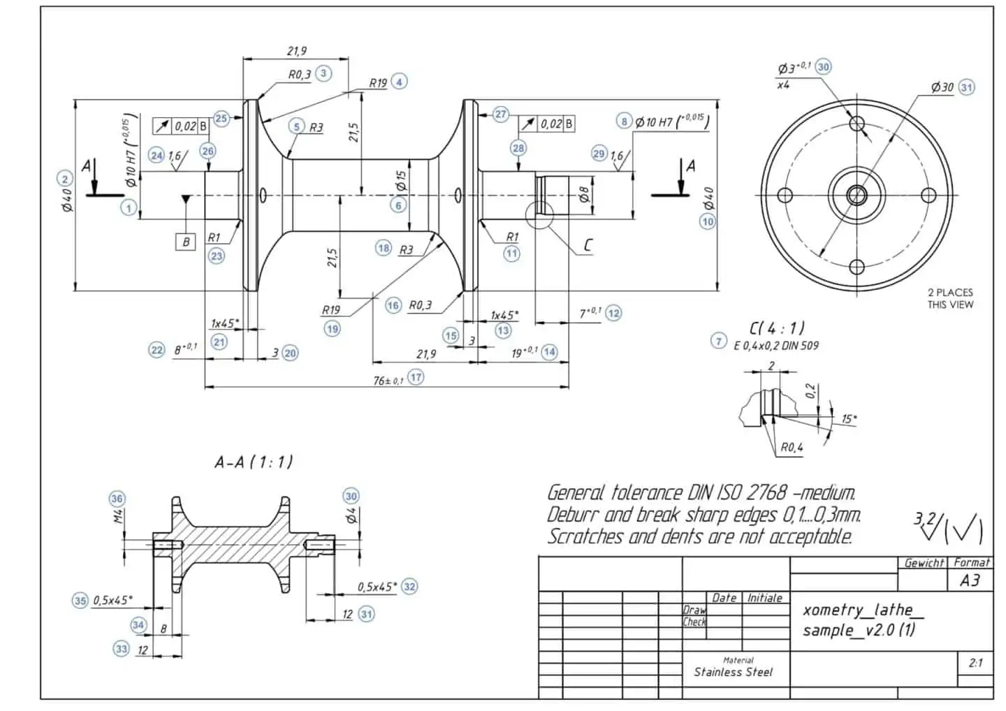
How To Prepare A Perfect Technical Drawing Xometry Europe
It indicates direction and extent of a dimension. We are going to look at what dimensioning is, what are the elements of the dimensions and what the rules for. To avoid confusion and the possibility of error, no dimension should be repeated twice on any sketch or drawing. Our comprehensive guide covers techniques, standards, and best practices for accuracy and.
![Dimensioning Its Types, System, Principles. [A Comprehensive Guide].](https://civilseek.com/wp-content/uploads/2018/10/dimensioning.jpg)
Dimensioning Its Types, System, Principles. [A Comprehensive Guide].
Web the new ipad pro — the thinnest apple product ever — features a stunningly thin and light design, taking portability to a whole new level. It indicates direction and extent of a dimension. Web three principles of dimensioning must be followed: All of these building blocks are equally important for defining the drawing clearly and unambiguously. In machine sketches.
Types Of Dimensions In Engineering Drawing at GetDrawings Free download
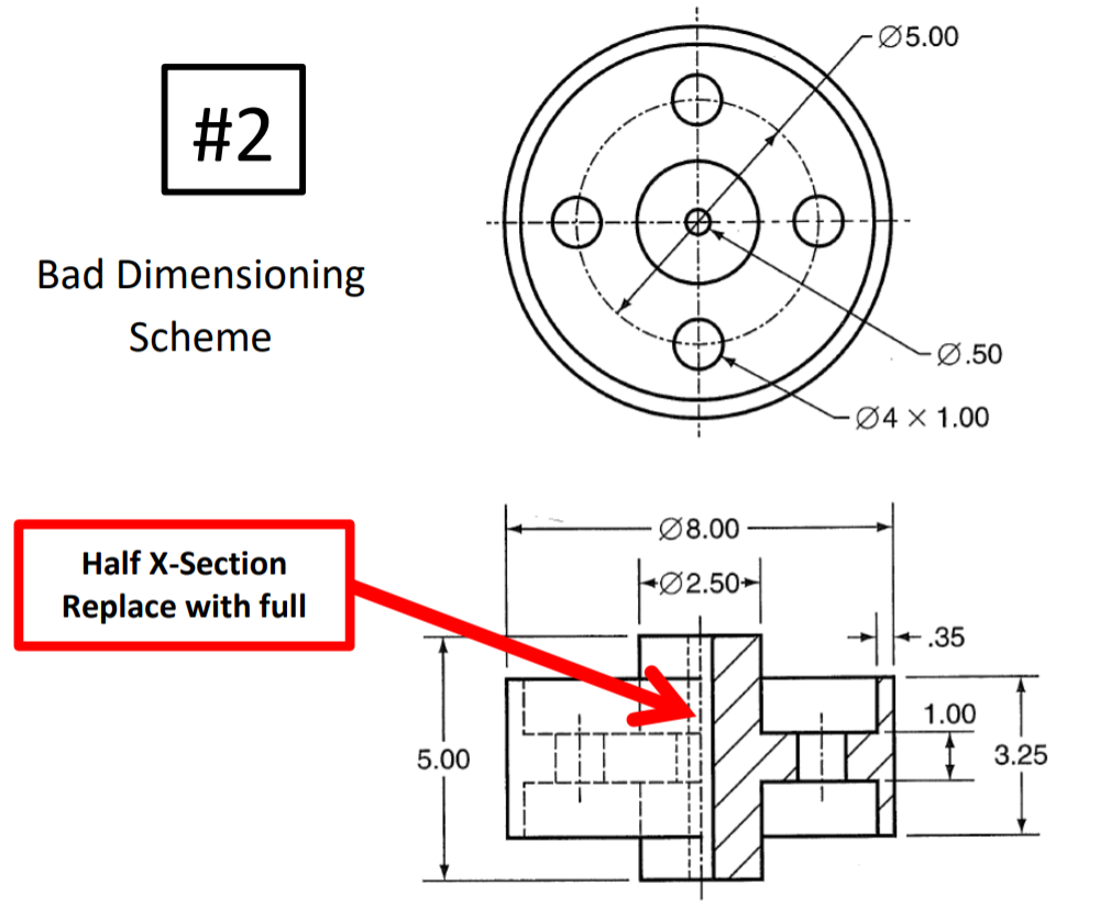
Web the purpose of dimensioning is to provide a clear and complete description of an object. Systems of dimensioning and tolerancing. To avoid confusion and the possibility of error, no dimension should be repeated twice on any sketch or drawing. Web in this video, we are going to learn about dimensions in engineering drawing! Dimensions in engineering drawings are numerical.
Dimensioning In Engineering Drawing Ppt
The dimension line is a fine, dark, solid line with arrowheads on each end. Engineering drawings and sketches need to display simplicity and. Web what is dimensioning in engineering drawing? Once the shape of a part is defined with an orthographic drawings, the size information is added also in the form of dimensions. Dimension — the numerical value that defines.
Web The Gsfc Engineering Drawing Standards Manual Is The Official Source For The Requirements And Interpretations To Be Used In The Development And Presentation Of Engineering Drawings And Related Documentation For The Gsfc.
Engineering drawings fundamentals introduces the fundamental concepts that are required to read, understand, and interpret engineering drawings used throughout the manufacturing industry. Dimensions in engineering drawings are numerical values indicated graphically in a proper unit of measurement on engineering drawing with lines, symbols, and notes. A circular arc is dimensioned by its radius using the symbol “r”. Dimensioning should follow these guidelines.
It Indicates Direction And Extent Of A Dimension.
Correct values must be given. Web in this video, we are going to learn about dimensions in engineering drawing! Using gd&t results in a more accurate design, larger tolerances for less important design features, and cost savings for manufacturing. Web essentially, dimensioning refers to the process of specifying the exact size, shape, and location of different parts and features on an engineering drawing.
In Introduction To The Engineering Drawings, We Showed You The Building Blocks Of The Engineering Drawing.
Web standards are formally published documents that establish consistent technical requirements for products, practices, methods, or operations, thereby ensuring uniformity, quality, and safety. To construct an object its shape and size must be known. We are going to look at what dimensioning is, what are the elements of the dimensions and what the rules for. A cylinder is dimensioned in side view using linear dimensions for both the length and diameter.
Asme Y14.37 2019 Product Definition For Composite Parts Standard.
To avoid confusion and the possibility of error, no dimension should be repeated twice on any sketch or drawing. In machine sketches and drawings, in which fractions and decimals are used for dimensions, the dimension line is usually broken near the middle to provide open space for the dimension numerals. All of these building blocks are equally important for defining the drawing clearly and unambiguously. Web asme y14.24 2020 types and applications of engineering drawings standard.