Engineering Drawing Notation
Engineering Drawing Notation - The requirements specified herein are essential to the standardization Web 3.4 symbols and notations. Alphanumeric characters used for labeling, numbering, and adding notes to the drawing. Note the comparison with the iso standards. Icons and figures that represent common features like welds, tolerances, finishes, etc. However, symbols can be meaningful only if they are created according to the relevant standards or conventions. They are a good visual representation of the desired item,. This is a complete guide to the types of holes found in machining. A generic engineering drawing can be divided into the following five major areas or parts. The purpose is to convey all the information necessary for manufacturing a product or a part.
(kbr), an engineering company, announced on monday that it has bagged a contract from oci global or oci to design and deploy its proprietary operator training simulator for. This manual sets forth the minimum requirements acceptable at gsfc for the preparation of engineering drawings for flight hardware and ground support systems. Engineering drawing employs a standardized set of symbols and notations: Engineering drawings use standardised language and symbols. The purpose of the standard is to ensure clear communication of detailed information. The title block appears either at the top or bottom of an engineering drawing. The symbols used for each hole and how they are shown on engineering drawings. Technical standards exist to provide glossaries of. Also in this drawing, two holes are identical, allowing the 2x notation to be used and the dimension to point to only one of the circles. The asme y14.5 standard establishes symbols, definitions, and rules for geometric dimensioning and tolerancing.
Eo 1.1 identify the symbols used on engineering p&ids for the following types of valves: Alphanumeric characters used for labeling, numbering, and adding notes to the drawing. The asme y14.5 standard establishes symbols, definitions, and rules for geometric dimensioning and tolerancing. Web any engineering drawing should show everything: It comes in useful if a feature is to be defined on a drawing that needs to be uniformly flat without tightening any other dimensions on the drawing. Web drafting symbols symbols provide a “common language” for drafters all over the world. Web unlike a 3d model, an engineering drawing offers a lot more specific information and requirements, including: The dimensions should be placed on the face that. [4] the name and contact information for the company producing or distributing the part. An engineering drawing is a type of technical drawing that is used to convey information about an object.

Engineering Drawing Symbols And Their Meanings Pdf at PaintingValley
Eo 1.1 identify the symbols used on engineering p&ids for the following types of valves: The easier way to achieve the best practice for technical drawing and cad described earlier using bim and autocad is to use annotative elements (annotative text, annotative dimensions, annotative leaders, etc.) those are annotative by default in bim software. Web engineering drawing abbreviations and symbols.
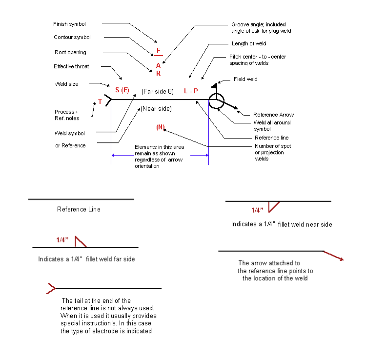
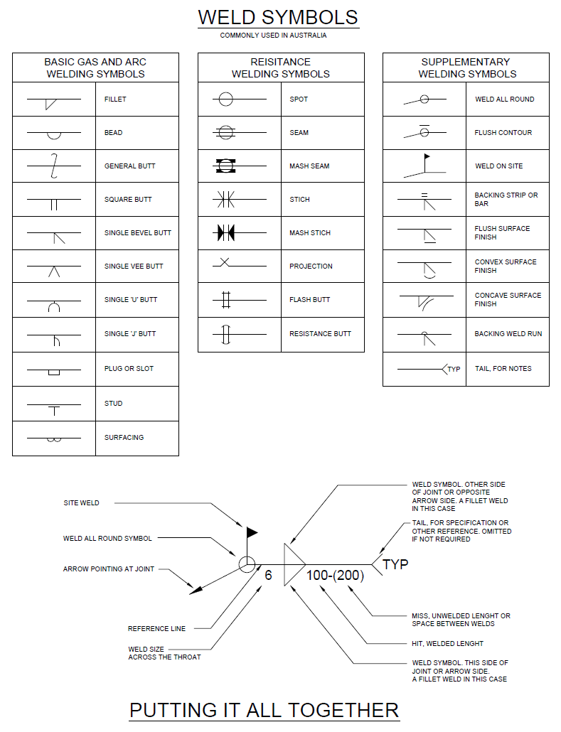
Understanding the Welding Symbols in Engineering Drawings Safe Work
How each type of hole is used in engineering. The requirements specified herein are essential to the standardization Web gd&t flatness is a common symbol that references how flat a surface is regardless of any other datum’s or features. However, symbols can be meaningful only if they are created according to the relevant standards or conventions. Eo 1.1 identify the.

Civil Engineering Drawing Symbols And Their Meanings at PaintingValley
A generic engineering drawing can be divided into the following five major areas or parts. Web unlike a 3d model, an engineering drawing offers a lot more specific information and requirements, including: Web asme y14.5 is an established, widely used gd&t standard containing all the necessary information for a comprehensive gd&t system. Web engineering and drafting personnel in the preparation,.

Engineering Drawing Symbols And Their Meanings Pdf at PaintingValley
Web asme y14.5 is an established, widely used gd&t standard containing all the necessary information for a comprehensive gd&t system. A complete understanding of the object should be possible from the drawing. The easier way to achieve the best practice for technical drawing and cad described earlier using bim and autocad is to use annotative elements (annotative text, annotative dimensions,.

How To Read Architectural Drawings Symbols The Architect
Engineering drawing employs a standardized set of symbols and notations: A common use is to specify the geometry necessary for the construction of a component and is called a detail drawing. What the difference is between counterbore and countersink holes. Surface texture symbols (y14.36) editions: But before learning how to read the actual drawing, an understanding of the.

ANSI Standard JSTD710 Architectural Drawing Symbols Bedrock Learning
Web drafting symbols symbols provide a “common language” for drafters all over the world. The easier way to achieve the best practice for technical drawing and cad described earlier using bim and autocad is to use annotative elements (annotative text, annotative dimensions, annotative leaders, etc.) those are annotative by default in bim software. The different types of holes used in.

Engineering Drawing Symbols And Their Meanings Pdf at PaintingValley
The dimensions should be placed on the face that. The title block appears either at the top or bottom of an engineering drawing. Most symbols have been in y14.5 since at least 1994. Learn the ins and outs of engineering drawing standards, such as iso and ansi, which govern the symbols, abbreviations, and notations used in. A complete understanding of.
Engineering Drawing Symbols And Their Meanings Pdf at PaintingValley
(kbr), an engineering company, announced on monday that it has bagged a contract from oci global or oci to design and deploy its proprietary operator training simulator for. Alphanumeric characters used for labeling, numbering, and adding notes to the drawing. How each type of hole is used in engineering. What the difference is between counterbore and countersink holes. Web engineering.

Technical Drawing Symbols And Their Meanings Design Talk
Surface texture symbols (y14.36) editions: To read and understand engineering fluid diagrams and prints, usually referred to as p&ids, an individual must be familiar with the basic symbols. Also in this drawing, two holes are identical, allowing the “2x” notation to be used and the dimension to point to only one of the circles. What the difference is between counterbore.

Mechanical Engineering Drawing Symbols Pdf Free Download at
Read this first to find out crucial information about the drawing, including: However, you still need to know. Technical standards exist to provide glossaries of. This makes understanding the drawings simple with little to no personal. The different types of holes used in machining.
Engineering Drawing Employs A Standardized Set Of Symbols And Notations:
Stay in the know with the latest methods, terms, applications, symbols, abbreviations and diagrams. (kbr), an engineering company, announced on monday that it has bagged a contract from oci global or oci to design and deploy its proprietary operator training simulator for. True position theory (size value in rectangular frame) The asme y14.5 standard establishes symbols, definitions, and rules for geometric dimensioning and tolerancing.
[4] The Name And Contact Information For The Company Producing Or Distributing The Part.
But before learning how to read the actual drawing, an understanding of the. This makes understanding the drawings simple with little to no personal. The dimensions should be placed on the face that. This document describes and illustrates common dimensioning, gd&t, architectural, piping, and electrical symbols.
Web Engineering Drawing Abbreviations And Symbols Are Used To Communicate And Detail The Characteristics Of An Engineering Drawing.
An engineering drawing is a subcategory of technical drawings. A generic engineering drawing can be divided into the following five major areas or parts. Engineering drawings use standardised language and symbols. A complete understanding of the object should be possible from the drawing.
Web A Good Design Drawing Can Indicate All The Details Needed To Produce A Mechanical Cnc Milling Part In An Easy Way.
Web gd&t drawings and symbols. The easier way to achieve the best practice for technical drawing and cad described earlier using bim and autocad is to use annotative elements (annotative text, annotative dimensions, annotative leaders, etc.) those are annotative by default in bim software. Icons and figures that represent common features like welds, tolerances, finishes, etc. The purpose of the standard is to ensure clear communication of detailed information.