Fillet Symbol In Engineering Drawing
Fillet Symbol In Engineering Drawing - Web 5 parts of the fillet weld. The reference line is a horizontal line that is used to align the other elements of the symbol. Hence, welding symbols are widely used in engineering drawings by. Web weld symbols are a key part of welding documentation, and understanding how to read weld symbols is critical for welders. This symbol is essential for communicating the. Fillet weld size is always placed on the left side of the fillet weld symbol as represented in the below example. Web subcontractors are often required to interpret weld symbols on engineering drawings, from perhaps the main contractor or client to determine the type of weld needed. Web when placing weld symbols on isometric views, remember the following: The leader of the symbol should be a short as possible to keep the information centralized. Web the weld_symbol_standard configuration option in the detail module enables you to set the symbol support for your drawings.
This symbol is essential for communicating the. There are three main elements to a weld symbol: Web subcontractors are often required to interpret weld symbols on engineering drawings, from perhaps the main contractor or client to determine the type of weld needed. If you will look at the graphical symbol of a fillet weld, you will see that there are five elements or parts to a fillet weld. Use the gas metal arc welding process. These welds can be applied on varying angles but this would be the most prominent. The radius value is given next to the symbol. • grooved—square, bevel, v, u, and j. Fillet weld size is always placed on the left side of the fillet weld symbol as represented in the below example. Fillet weld symbol ( ):
If you will look at the graphical symbol of a fillet weld, you will see that there are five elements or parts to a fillet weld. These are symbols used to indicate welding methods, weld form, and weld size, among other technical content on a drawing. Web fillet (mechanics) in mechanical engineering, a fillet is a rounding of an interior or exterior corner of a part designed in cad. An interior or exterior corner, with an angle or type of bevel, is called a chamfer. Components of welding symbols (1) weld symbols: Web when you see an engineering fabrication drawing, you will notice several welding symbols on the drawing. The groove weld symbol indicates a weld made in a groove or channel. For example, a 0.5 inch fillet radius would be represented as. The reference line is a horizontal line that is used to align the other elements of the symbol. If the welds are symmetrical on both sides of the.
Fillet Weld Symbols Chart IMAGESEE
These welds can be applied on varying angles but this would be the most prominent. It is also in paragraph 3.3.18 of the 1994 spec with the word profile missing, but in reference to a tolerance, verses a dimension. Fillet welds are one of the most common weld types in the industry. Serving to indicate the precise location of the.
Fillet Weld Symbols On Drawings
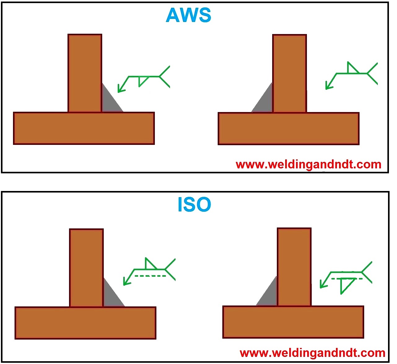
If the two legs of the fillet weld are different, then the. The weld symbol should not over a part or assembly, always lave the weld symbol net, above or below the view. For bevel and v symbols, if root_open is more than zero, the steep version of the. Web compare these two symbols. They are placed on welding drawings.
AutoCAD Fillet Command Applying Fillets to 2D and 3D Objects CAD CAM
Web the need for consistency in both the application of welding symbols to engineering drawings, and the accurate interpretation by personnel directly involved in manufacturing or construction, led to the development of a standard for these activities. Note what is different and what each one means: In engineering drawings, fillets and rounds are typically specified using dimensional tolerances and geometrical.
![[SOLVED] In engineering drawing, the welding symbol used for fillet](https://storage.googleapis.com/tb-img/production/20/08/weld symbol1.PNG)
[SOLVED] In engineering drawing, the welding symbol used for fillet
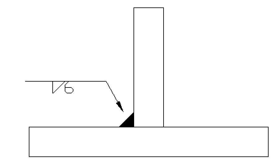
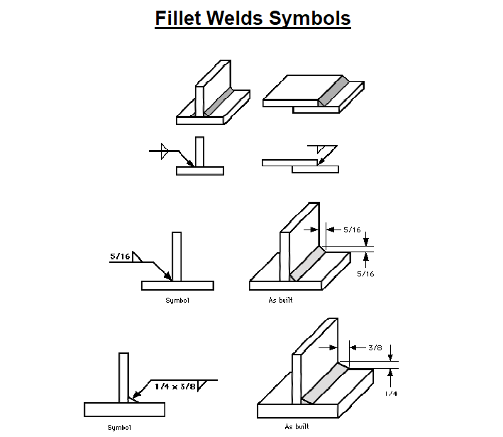
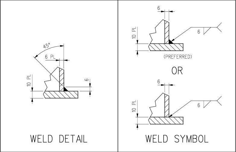
Web the symbol used to represent fillet welding in blueprints and engineering drawings consists of several elements.the symbol is usually accompanied by a dimension line, which indicates the size of the fillet weld. 10mm fillet weld other side of arrow. A fillet weld symbol can be used with an arrow side. Fillet welds are one of the most common weld.
Understanding the Welding Symbols in Engineering Drawings Safe Work
Web compare these two symbols. For bevel and v symbols, if root_open is more than zero, the steep version of the. Web welding symbols are a graphical way to convey information about a welding joint. Web welding symbols, like sign posts are informational directors. If the welds are symmetrical on both sides of the.
1.6 Fillet Weld Symbols Workforce LibreTexts
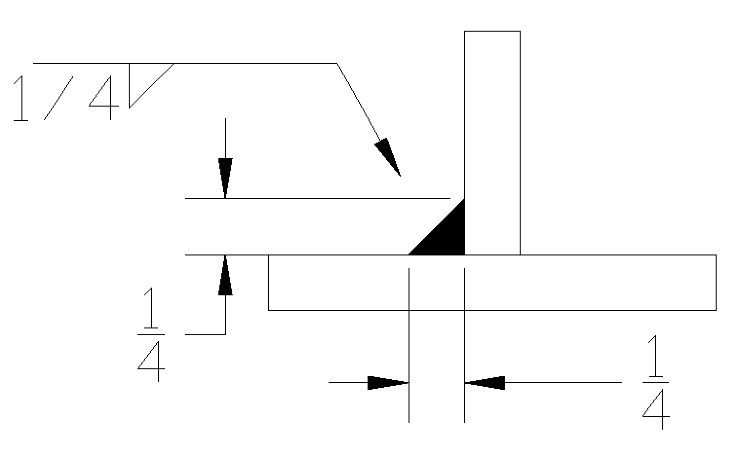
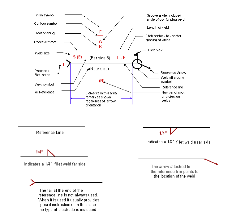
Web welding symbols, like sign posts are informational directors. Web placing fillet weld size & length in a weld symbol. The vertical leg of the symbol will always be placed to the left. Web during metal joining processes, weld symbols are meant to indicate different parts of the process. These elements include the throat, leg, face, toe, and root.
Welding Symbols Chart An Explanation of the Basics (with Pictures
The fillet weld symbol is a right triangle placed on the reference line with the. Web placing fillet weld size & length in a weld symbol. Instead of using an arrow and saying ‘weld here’, a weld symbol carries more useful information that can be easily understood by the welder, engineer, foreman, supervisor and architect. These welds can be applied.
Fillet Weld Symbols Interpretation of Metal Fab Drawings
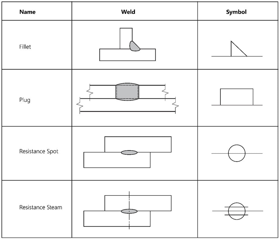
Use the gas metal arc welding process. Some commonly used welding symbols include: Fillet welds are one of the most common weld types in the industry. Keep the symbol uncluttered where it can be easily visible. Web fillet on a sand casting pattern.
Dimensioning of welds Engineering Drawing Basics
Components of welding symbols (1) weld symbols: Web welding symbols are a graphical way to convey information about a welding joint. The fillet weld symbol is a right triangle placed on the reference line with the. The following weld symbols are supported in iso: The groove weld symbol indicates a weld made in a groove or channel.
Understanding the Welding Symbols in Engineering Drawings Safe Work
Fillet weld size is always placed on the left side of the fillet weld symbol as represented in the below example. Fillets and rounds are specified using the “radius” symbol, “r”. For example, a 0.5 inch fillet radius would be represented as. If length is not specified, it means welding has to be deposited in the full. The vertical leg.
A Fillet Is Indicated On A Drawing In The Same Way As A Round, Illustrated In Figure 2, With A Dimension That Includes The Radius Symbol And Radius Length.
In many instances the information relayed is very simple. 10mm fillet weld other side of arrow. The reference line is a horizontal line that is used to align the other elements of the symbol. If length is not specified, it means welding has to be deposited in the full.
Web The Weld_Symbol_Standard Configuration Option In The Detail Module Enables You To Set The Symbol Support For Your Drawings.
Web when placing weld symbols on isometric views, remember the following: Fillet geometry, when on an interior corner is a line of concave function, whereas a fillet on an exterior corner is a line of. If you will look at the graphical symbol of a fillet weld, you will see that there are five elements or parts to a fillet weld. Fillet weld symbol ( ):
Web 5 Parts Of The Fillet Weld.
In engineering drawings, fillets and rounds are typically specified using dimensional tolerances and geometrical tolerance symbols. These are a set of symbols that describe the weld, the weld leg size, as well as giving processing and finishing information. The weld symbol should not over a part or assembly, always lave the weld symbol net, above or below the view. The vertical leg of the symbol will always be placed to the left.
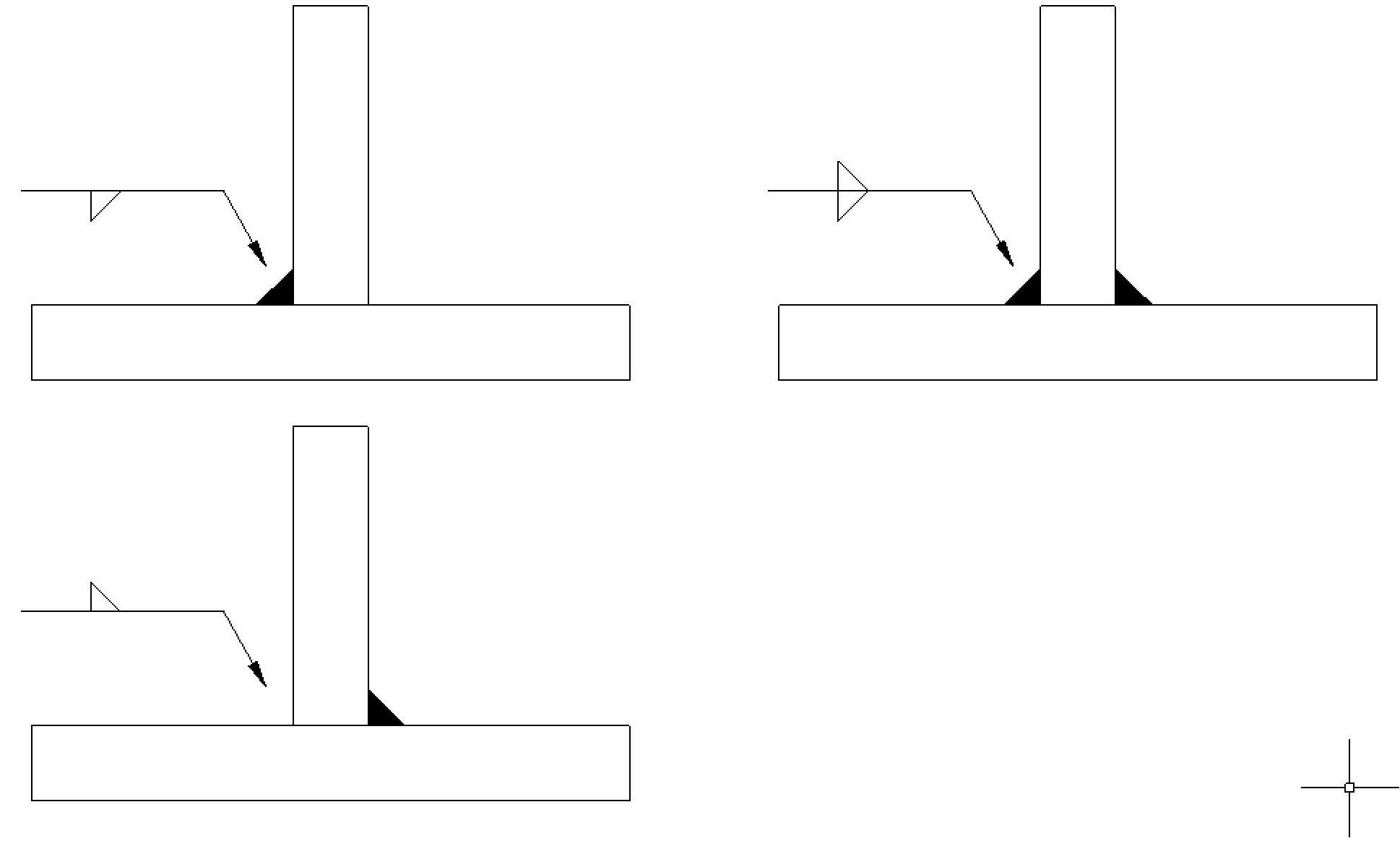
Weld Symbols On The Full Reference Line Relates To Welds On The Near Side Of The Plate Being Welded.
A fillet weld symbol can be used with an arrow side. The new 2009 spec also applies it in paragragh 3.3.19 relatuve to profile tolerance of all surfaces. Weld symbols on the dashed line relates to weld on the far side of the plate. It is also in paragraph 3.3.18 of the 1994 spec with the word profile missing, but in reference to a tolerance, verses a dimension.