Gd And T Drawings
Gd And T Drawings - Web a very common issue that we see on gd&t drawings is the failure to indicate which gd&t standard is being applied. Web gd&t is a particular set of conventions used on engineering drawings (often called “prints” from the older “blueprints”) that communicate how parts should fit together and how they function. Web this page explains the 16 symbols used in gd&t, and the classification thereof. “learning gd&t from scratch,” provided by keyence, walks you through the basics of geometric dimensioning and tolerancing, datums, and measurements by coordinate measuring. Web this videos covers the different geometric characteristics and other key aspects of gd&t including datums, material modifiers (mmc, lmc and rfs), the envelope principle (also called gd&t rule #1. Understand commonly used gd&t symbols & terms. Web gd&t is an international language used on engineering drawings. Web gd&t symbols and definitions help convey the designed object and allow for the manufacturing of mechanical parts in a way that improves quality, lowers manufacturing costs, and shortens delivery time. Gd&t controls variations of size, form, orientation, location and runout individually or in combination. Web a convenient guide for geometric dimensioning and tolerancing (gd&t) symbols at your fingertips.
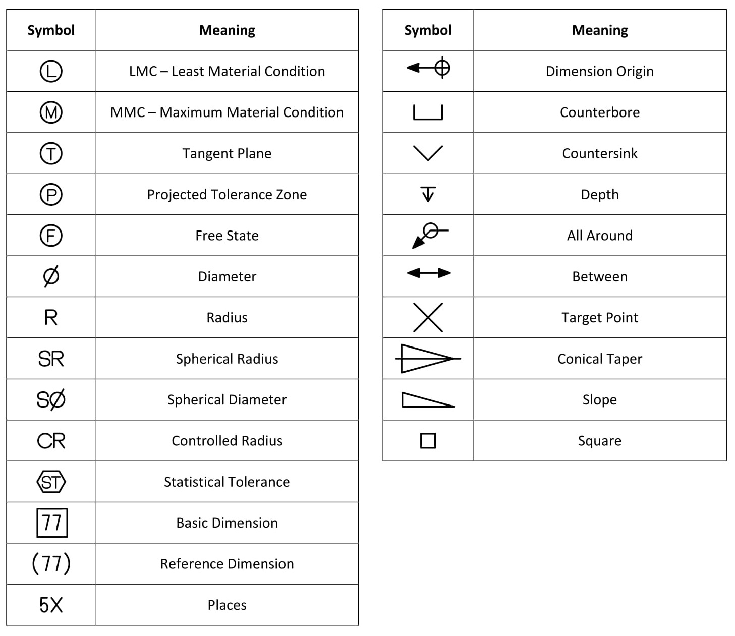
These are grouped into symbols relating to form, profile, orientation, runout and location. Web this page explains the 16 symbols used in gd&t, and the classification thereof. If you are involved in design or manufacturing, you may be familiar with the term, “gd&t,” or “geometric dimensioning and tolerancing”. Distinguish between a feature and a datum. The concept of gd&t was adopted by the military in the 1950s and is now in use in multiple industries around the world. “learning gd&t from scratch,” provided by keyence, walks you through the basics of geometric dimensioning and tolerancing, datums, and measurements by coordinate measuring. A part drawing may include a single gd&t callout, or the drawing may be fully defined using gd&t depending on part requirements. In this video, jason highlights the importance of indicating the standard being used and how to. What is geometric dimensioning & tolerancing (gd&t) Common gd&t symbols are listed in the table below.
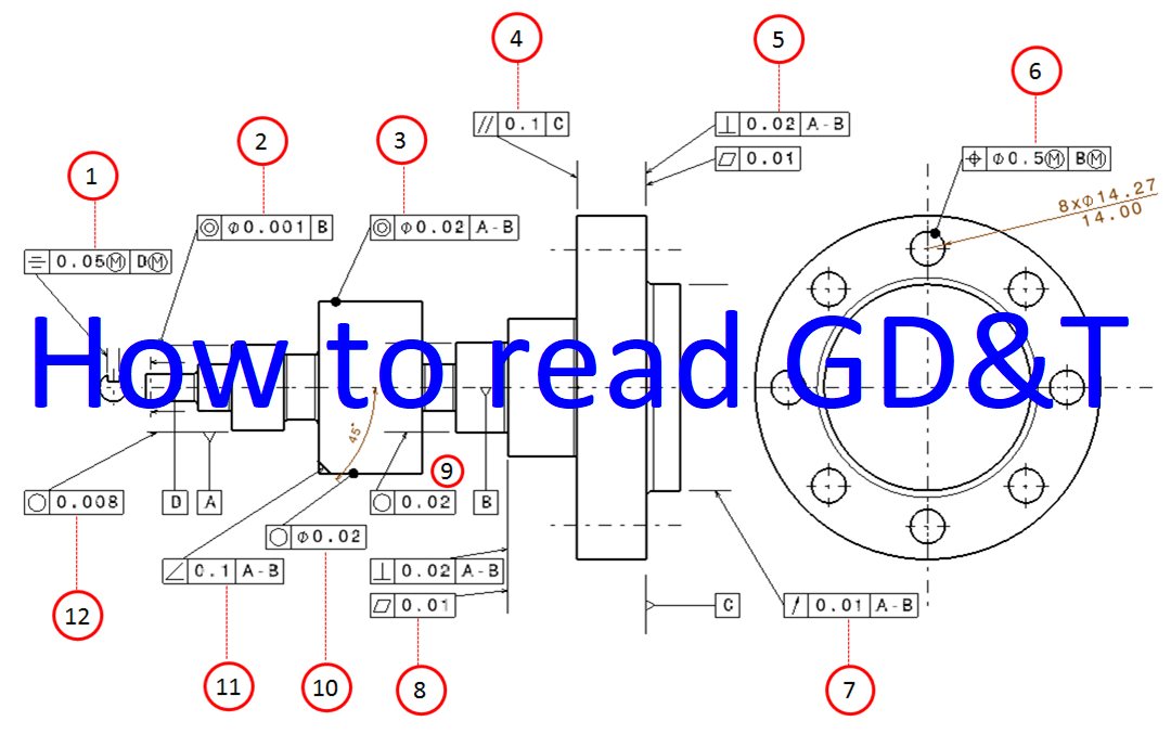
Describe the scope of gd&t standards. Web let's understand the step by step approach to do gd&t for mechanical drawing.understand difference between general dimensioning and tolerancing.understand th. A part drawing may include a single gd&t callout, or the drawing may be fully defined using gd&t depending on part requirements. This course will teach you the basics of how to understand gd&t symbols and their use. Web gd&t ( geometrical dimensions and tolerances ) is the new vocabulary of engineering drawings. Web what is gd&t? Understand when and why gd&t is used. Web gd&t symbols and definitions help convey the designed object and allow for the manufacturing of mechanical parts in a way that improves quality, lowers manufacturing costs, and shortens delivery time. “learning gd&t from scratch,” provided by keyence, walks you through the basics of geometric dimensioning and tolerancing, datums, and measurements by coordinate measuring. The concept of gd&t was adopted by the military in the 1950s and is now in use in multiple industries around the world.
GD&T Drawings KOHLEX
This course will teach you the basics of how to understand gd&t symbols and their use. In this video, jason highlights the importance of indicating the standard being used and how to. The true position theory and the specification of tolerance zones are also explained. As with all new systems, there is a learning curve with gd&t. Web gd&t is.

GD&T The Beginner's Guide to Geometric Dimensioning and Tolerancing
Describe the scope of gd&t standards. Web what is gd&t? Web gd&t is an international language used on engineering drawings. Parker’s determination of position (or true position) has since grown to include other concepts including flatness, profile, runout, roundness and much more. Web a very common issue that we see on gd&t drawings is the failure to indicate which gd&t.

GD&T Basics What You Need to Know
These are grouped into symbols relating to form, profile, orientation, runout and location. Web this page explains the 16 symbols used in gd&t, and the classification thereof. What is geometric dimensioning & tolerancing (gd&t) Web let's understand the step by step approach to do gd&t for mechanical drawing.understand difference between general dimensioning and tolerancing.understand th. Web this videos covers the.
What are Geometric dimensioning and tolerancing GD & T Symbols
The true position theory and the specification of tolerance zones are also explained. Gd&t controls variations of size, form, orientation, location and runout individually or in combination. Common gd&t symbols are listed in the table below. Web gd&t is an international language used on engineering drawings. Understand when and why gd&t is used.
Design Tech Academy (1)Geometric Dimensioning and Tolerancing (GD&T
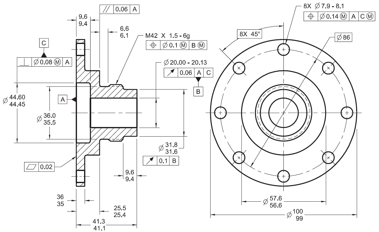
Web geometric dimensioning and tolerancing (gd&t) is a system of symbols and standards used in engineering drawings and models to specify the required form, size, orientation, and location of parts and features. Web this page explains the 16 symbols used in gd&t, and the classification thereof. Web the gd&t methodology was created to standardize the “language” of engineering drawings, so.

GD&T for beginners step by step approach to do gd&t for mechanical
Web this page shows a list of gd&t symbols and associated symbols used by iso and asme. By providing uniformity in drawing specifications and interpretation, geometric dimensioning and tolerancing reduces controversy, guesswork, and assumptions throughout the manufacturing and inspection process. Web gd&t ( geometrical dimensions and tolerances ) is the new vocabulary of engineering drawings. Web gd&t symbols and definitions.
Examples on how to interpret GD&T Form, orientation, location and run
The true position theory and the specification of tolerance zones are also explained. Web gd&t is a particular set of conventions used on engineering drawings (often called “prints” from the older “blueprints”) that communicate how parts should fit together and how they function. Web a convenient guide for geometric dimensioning and tolerancing (gd&t) symbols at your fingertips. This course will.

GD&T 101 An Introduction to Geometric Dimensioning and Tolerancing
Web gd&t symbols and definitions help convey the designed object and allow for the manufacturing of mechanical parts in a way that improves quality, lowers manufacturing costs, and shortens delivery time. This is the language that your drawings speak. Web let's understand the step by step approach to do gd&t for mechanical drawing.understand difference between general dimensioning and tolerancing.understand th..

Engineering Drawings & GD&T For the Quality Engineer Mechanical
Web gd&t is an international language used on engineering drawings. Web gd&t ( geometrical dimensions and tolerances ) is the new vocabulary of engineering drawings. Web what is gd&t? Web let's understand the step by step approach to do gd&t for mechanical drawing.understand difference between general dimensioning and tolerancing.understand th. In some cases, different terms may refer to the same.

GD&T Tips Profile As a General Tolerance
Web gd&t symbols and definitions help convey the designed object and allow for the manufacturing of mechanical parts in a way that improves quality, lowers manufacturing costs, and shortens delivery time. “learning gd&t from scratch,” provided by keyence, walks you through the basics of geometric dimensioning and tolerancing, datums, and measurements by coordinate measuring. Distinguish between a feature and a.
These Are Grouped Into Symbols Relating To Form, Profile, Orientation, Runout And Location.
Geometric dimensioning and tolerancing is a set of rules and gd&t symbols used on a drawing to communicate the intent of a design, focusing on the function of the part. Parker’s determination of position (or true position) has since grown to include other concepts including flatness, profile, runout, roundness and much more. Web this videos covers the different geometric characteristics and other key aspects of gd&t including datums, material modifiers (mmc, lmc and rfs), the envelope principle (also called gd&t rule #1. In some cases, different terms may refer to the same concept (e.g.
Web This Page Explains The 16 Symbols Used In Gd&T, And The Classification Thereof.
Web this page shows a list of gd&t symbols and associated symbols used by iso and asme. Web a convenient guide for geometric dimensioning and tolerancing (gd&t) symbols at your fingertips. Describe the scope of gd&t standards. This course will teach you the basics of how to understand gd&t symbols and their use.
As With All New Systems, There Is A Learning Curve With Gd&T.
Click on the links below to learn more about each gd&t symbol or concept, and be sure to download the free wall chart for a quick reference when at. Web gd&t symbols use to communicate accuracy and precision information form designer to manufactures through engineering drawings. Web gd&t is a particular set of conventions used on engineering drawings (often called “prints” from the older “blueprints”) that communicate how parts should fit together and how they function. Common gd&t symbols are listed in the table below.
Distinguish Between A Feature And A Datum.
Web what is gd&t? Web gd&t is an international language used on engineering drawings. Web gd&t symbols and definitions help convey the designed object and allow for the manufacturing of mechanical parts in a way that improves quality, lowers manufacturing costs, and shortens delivery time. Understand when and why gd&t is used.