Gdt Drawings
Gdt Drawings - Geometric dimensioning and tolerancing (gd&t or gd and t) is a language of symbols and standards designed and used by engineers and manufacturers to describe the shape (geometry) and size (dimensions) of a product and facilitate communication between entities working together to manufacture products. Web the content has been updated. Drawing views are simply the representation of your. The following tolerance applies to all. Web want to watch bonus the efficient engineer video that aren't on youtube? Web let sae provide gd&t training and materials for your organization. Gd&t allows designers to place only the needed controls and tolerances on features. It is an important tool for ensuring the interchangeability, functional accuracy, and reliability of manufactured components. Web geometric dimensioning and tolerancing is used to communicate detailed information on technical drawings. Web in gd&t, each feature of a manufactured part is specified by datums and controls.
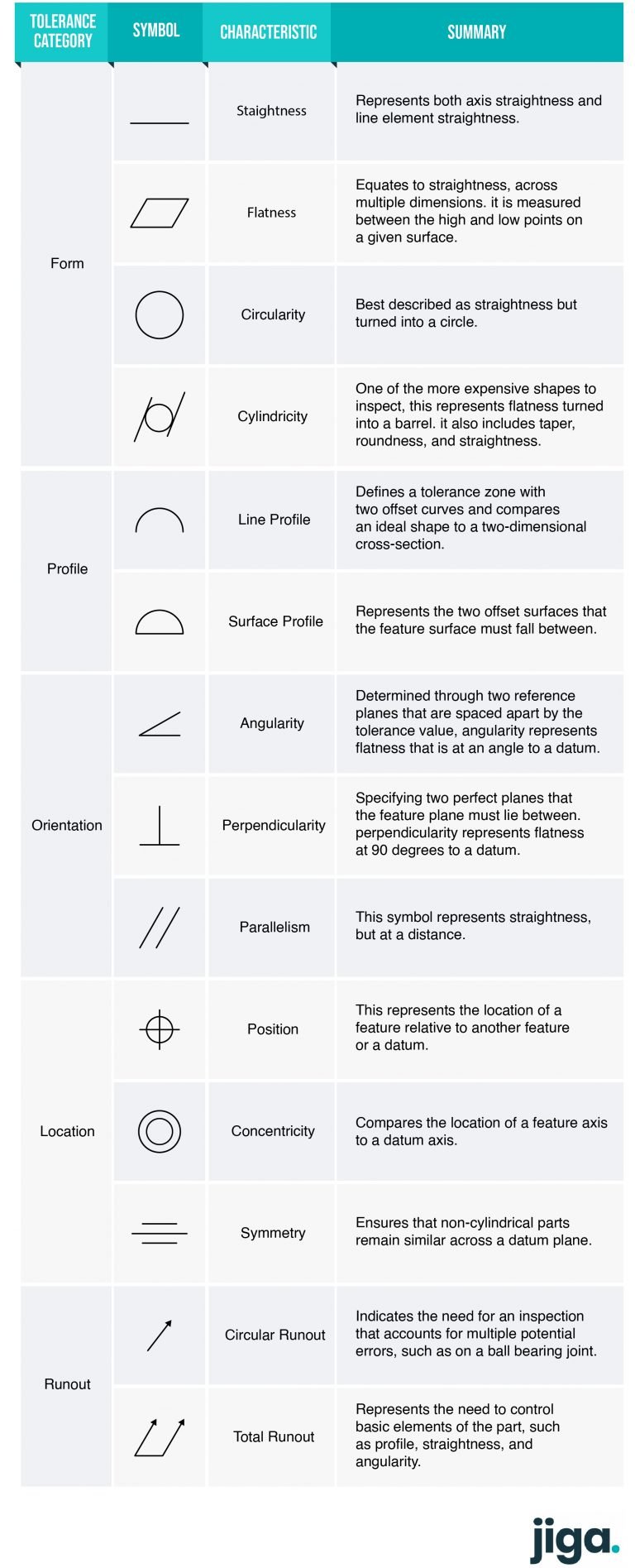
It comes in useful if a feature is to be defined on a drawing that needs to be uniformly flat without tightening any other dimensions on the drawing. Refer to the provided cad data, , for basic dimensions. Parallelism is a fairly common symbol that describes a parallel orientation of one referenced feature to a datum surface or line. Currently, we have 16 symbols for geometric tolerances, which are categorized according to the tolerance they specify. The purpose of this standard is to establish requirements of industry and provide a way to communicate drawing objective as per project specifications. Praniewicz (nist) 18 notes 1. Geometric dimensioning and tolerancing is a set of rules and gd&t symbols used on a drawing to communicate the intent of a design, focusing on the function of the part. Gd&t tells the manufacturer the degree of accuracy and precision needed for each controlled feature of the part. Web gd&t drawings and symbols. Standardization of gd&t and knowledge of those standards is crucial to ensure that the design intent is communicated properly.
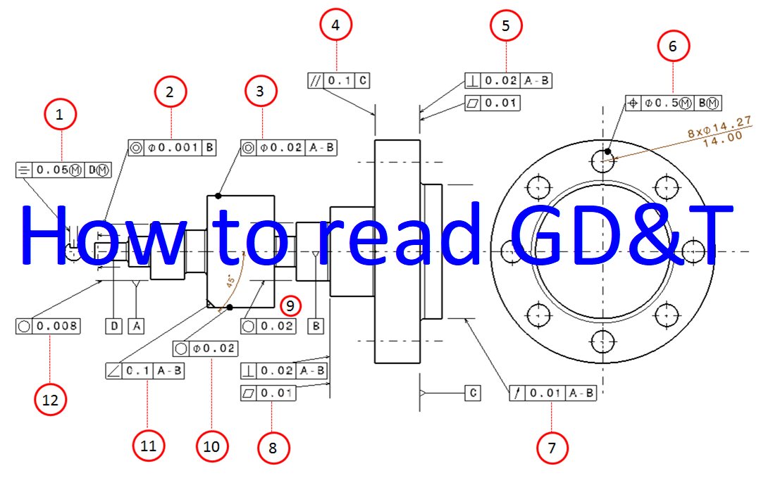
The purpose of this standard is to establish requirements of industry and provide a way to communicate drawing objective as per project specifications. Geometric tolerances are specified using symbols on a drawing. True position theory (size value in rectangular frame) The following tolerance applies to all. Asme y14.5 is an established, widely used gd&t standard containing all the necessary information. Geometric dimensioning and tolerancing (gd&t or gd and t) is a language of symbols and standards designed and used by engineers and manufacturers to describe the shape (geometry) and size (dimensions) of a product and facilitate communication between entities working together to manufacture products. Yes mmc or lmc applicable: Web want to watch bonus the efficient engineer video that aren't on youtube? Web gd&t aims to communicate the design intent in a way that the desired form, fit, function, and interchangeability of feature is conveyed on the drawings without confusion. Gd&t tells the manufacturer the degree of accuracy and precision needed for each controlled feature of the part.

GD&T Basics What You Need to Know
Web gd&t aims to communicate the design intent in a way that the desired form, fit, function, and interchangeability of feature is conveyed on the drawings without confusion. Views, dimensions, tolerances, symbols, datum’s, feature control frames & title blocks. Our gd&t guided study courses enhance your skills related to choosing datums and feature controls, per asme y14.5, through drawing assignments,.
GD&T (Geometric Dimensioning and Tolerancing) Guide Jiga
Geometric tolerances are specified using symbols on a drawing. Web gd&t flatness is a common symbol that references how flat a surface is regardless of any other datum’s or features. The flatness tolerance references two parallel planes (parallel to the surface. It is an important tool for ensuring the interchangeability, functional accuracy, and reliability of manufactured components. Web gd&t aims.

GD&T Drawings KOHLEX
Web gd&t drawings and symbols. Currently, we have 16 symbols for geometric tolerances, which are categorized according to the tolerance they specify. This is a minimally dimensioned drawing. Web gd&t flatness is a common symbol that references how flat a surface is regardless of any other datum’s or features. Web geometric dimensioning and tolerancing (gd&t) is a system of symbols.

GD&T Symbols With Examples
Yes mmc or lmc applicable: True position theory (size value in rectangular frame) This is a minimally dimensioned drawing. Web gd&t drawing callout: You’ll learn practical skills you’ll use every day on the job.

GD&T for beginners step by step approach to do gd&t for mechanical
Currently, we have 16 symbols for geometric tolerances, which are categorised according to the tolerance they specify. Geometric dimensioning and tolerancing (gd&t or gd and t) is a language of symbols and standards designed and used by engineers and manufacturers to describe the shape (geometry) and size (dimensions) of a product and facilitate communication between entities working together to manufacture.

GD&T The Beginner's Guide to Geometric Dimensioning and Tolerancing
Classification and symbols of geometric tolerance characteristics. Standardization of gd&t and knowledge of those standards is crucial to ensure that the design intent is communicated properly. If gd&t seems complex, it is only because there is a long list of ways a physical part can deviate from the geometric ideal of what the designer had in mind. There are 7.

GD&T Tips Profile As a General Tolerance
Gd&t is used to define the nominal (theoretically. Web geometric dimensioning and tolerancing (gd&t) is a system of symbols used on engineering drawings to communicate information from the designer to the manufacturer through engineering drawings. Web want to watch bonus the efficient engineer video that aren't on youtube? The flatness tolerance references two parallel planes (parallel to the surface. Geometric.
Examples on how to interpret GD&T Form, orientation, location and run
Web geometric dimensioning and tolerancing (gd&t) is a system of symbols used on engineering drawings to communicate information from the designer to the manufacturer through engineering drawings. There are 7 aspects of the gd&t methodology that we will discuss, these include: Web geometric dimensioning and tolerancing (gd&t) is a system of symbols and standards used in engineering drawings and models.
GD&T Drawings KOHLEX
You’ll learn practical skills you’ll use every day on the job. Web gd&t drawing callout: Geometric dimensioning and tolerancing is a set of rules and gd&t symbols used on a drawing to communicate the intent of a design, focusing on the function of the part. Standardization of gd&t and knowledge of those standards is crucial to ensure that the design.

GD&T 101 An Introduction to Geometric Dimensioning and Tolerancing
Geometric dimensioning and tolerancing (gd&t or gd and t) is a language of symbols and standards designed and used by engineers and manufacturers to describe the shape (geometry) and size (dimensions) of a product and facilitate communication between entities working together to manufacture products. Geometric tolerances are specified using symbols on a drawing. Parallelism is a fairly common symbol that.
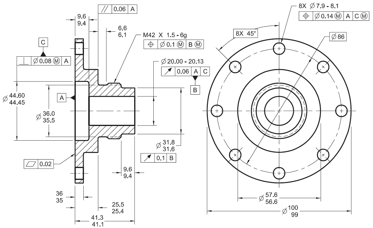
Web A Simple Drawing With Gd&T Symbols.
Web in gd&t, each feature of a manufactured part is specified by datums and controls. Praniewicz (nist) 18 notes 1. If gd&t seems complex, it is only because there is a long list of ways a physical part can deviate from the geometric ideal of what the designer had in mind. Web gd&t is a way for engineers and designers to more accurately control features and tolerances on manufacturing drawings.
Web With The Dimension Scheme Completed, Add Individual Geometric Tolerances And Gd&T Symbols.
Web if you are involved in design or manufacturing, you may be familiar with the term, “gd&t,” or “geometric dimensioning and tolerancing”. Gd&t tells the manufacturer the degree of accuracy and precision needed for each controlled feature of the part. Asme y14.5 is an established, widely used gd&t standard containing all the necessary information. Web gd&t drawings and symbols.
Our Gd&T Guided Study Courses Enhance Your Skills Related To Choosing Datums And Feature Controls, Per Asme Y14.5, Through Drawing Assignments, Quizzes, And Email Q&A With An Expert Instructor.
Geometric dimensioning and tolerancing (gd&t or gd and t) is a language of symbols and standards designed and used by engineers and manufacturers to describe the shape (geometry) and size (dimensions) of a product and facilitate communication between entities working together to manufacture products. Web geometric dimensioning and tolerancing (gd&t) is a system of symbols and standards used in engineering drawings and models to specify the required form, size, orientation, and location of parts and features. Gd&t allows designers to place only the needed controls and tolerances on features. Standardization of gd&t and knowledge of those standards is crucial to ensure that the design intent is communicated properly.
We Can Incorporate Your Company Drawings Into A One Day Gd&T Review And Application Course.
This is a minimally dimensioned drawing. Make sure to select ‘bilateral’ or ‘limit’ as tolerance type for features where the plus and minus limit are unequal. Currently, we have 16 symbols for geometric tolerances, which are categorised according to the tolerance they specify. Web geometric dimensioning and tolerancing is used to communicate detailed information on technical drawings.