How To Draw A Phasor Diagram
How To Draw A Phasor Diagram - Drag and drop the phasors. Web phasor diagram (& its applications) phasors are rotating vectors having the length equal to the peak value of oscillations, and the angular speed equal to the angular frequency of the oscillations. In case of series rlc circuit; Phasor addition of two phasors. Web how to draw a phasor diagram? Web the total voltage, v t of the two voltages can be found by firstly drawing a phasor diagram representing the two vectors and then constructing a parallelogram in which two of the sides are the voltages, v 1 and v 2 as shown below. It is customary to draw the phasor representing current horizontally, and call this the reference phasor. Web the process of drawing a phasor diagram involves identifying ac circuit elements, plotting the reference and other vectors, adding complex numbers, and interpreting the vectors. Web in this video of phasor diagram following topic has been covered!1. After entering the values, you can use the online tool’s drawing tools to drag and drop the phasors on the diagram.
Phasor diagrams are used in simple harmonic. Web phasors are rotating vectors having the length equal to the peak value of oscillations, and the angular speed equal to the angular frequency of the oscillati. Drag and drop the phasors. For drawing the phasor diagram, take current phasor as reference and draw it on horizontal. After entering the values, you can use the online tool’s drawing tools to drag and drop the phasors on the diagram. Web this video provides a very easy concept of drawing phasor diagram for any complex network. Resistor, capacitor and inductor are connected in series; Web this includes the amplitude, frequency, and phase of each component. Web how to draw a phasor diagram of any circuit is discussed here step by step.subscribe my new channel here : And at the end, voltage and current relationship between the basic circuit ele.
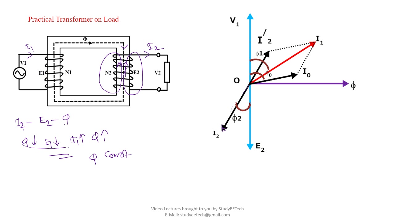
The magnitude and phase of each wave can then be drawn as a vector, and the relationships between the waves is shown directly. Web in this video, phasor, and phasor diagram for ac circuits have been explained. Imagine that the phasors are rotating in an anticlockwise (counter clockwise) direction. Since the transformer windings are inductive, the input voltage v p leads the magnetizing current (i mag) by 90°. Increased accuracy in phasor diagrams can be achieved by ensuring calculations are correct, vectors are_marked clearly, the right reference vector is chosen, the tools. Web learn how to draw phasor diagrams, representing sinusoidal quantities with magnitude and phase angles. They are also a useful tool to add/subtract oscillations. Resistor in case of resistor, the voltage and the current are in same phase or we can say that the phase angle difference between voltage and current is zero.; Phasor diagrams can be used to analyze various. Web this includes the amplitude, frequency, and phase of each component.
How to Draw Transformer Phasor Diagram YouTube
Every phasor in the diagram will have the same. Web how to draw a phasor diagram of any circuit is discussed here step by step.subscribe my new channel here : Web the process of drawing a phasor diagram involves identifying ac circuit elements, plotting the reference and other vectors, adding complex numbers, and interpreting the vectors. Web in this video,.

How to draw a Phasor Diagram ? Step by Step Tech TALKS YouTube
They are helpful in depicting the phase relationships between two or more oscillations. Web a phasor diagram is used to show the phase relationships between two or more sine waves having the same frequency. This arrow would start at the origin of the cartesian coordinate system and point in the direction of the angle. Since the transformer windings are inductive,.

Phasor Diagram For Inductive Circuit
Web how to draw a phasor diagram? Phasor diagrams are used in simple harmonic. Web this video provides a very easy concept of drawing phasor diagram for any complex network. Phasor diagrams can be used to analyze various. In circuits which have l, c, r connected in series.

How To Work & Draw Phasor Diagram Of Transformer At No Load YouTube
Web how to draw a phasor diagram? You may also need to specify the number of components and their relative positions in the diagram. Master the techniques of adding phasors graphically or mathematically to analyze ac circuits effectively. What is phasor diagram 3. Web how to draw a phasor diagram of any circuit is discussed here step by step.subscribe my.
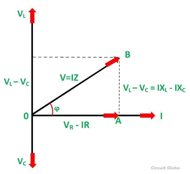
What is RLC Series Circuit? Phasor Diagram & Impedance Triangle
The phasor diagram is based on the complex plane discussed previously where the horizontal is the real axis and the vertical is the imaginary ( j j) axis. Graph functions, plot points, visualize algebraic equations, add sliders, animate graphs, and more. Resistor in case of resistor, the voltage and the current are in same phase or we can say that.

How to draw phasor diagram from polar form phasors ? Electrical
In circuits which have l, c, r connected in series. There are five rules for drawing phasor diagrams. A vector is a line that, by its length and direction, represents the magnitude and angle of application of a force or velocity or other. They are helpful in depicting the phase relationships between two or more oscillations. Resistor in case of.
How To Draw A Phasor Diagram Free Wiring Diagram
Web in this video, phasor, and phasor diagram for ac circuits have been explained. Web phasors are rotating vectors having the length equal to the peak value of oscillations, and the angular speed equal to the angular frequency of the oscillati. Web phasor diagrams are a representation of an oscillating quantity as a vector rotating in phase space with an.

how to draw phasor diagram ? how to draw phasor diagram ? YouTube
Web explore math with our beautiful, free online graphing calculator. For drawing the phasor diagram, take current phasor as reference and draw it on horizontal. Continuing with the previous example, we can draw an arrow of length 5 units at an angle of 30 degrees above the horizontal axis to represent the complex number 5 + j0.866. The magnitude and.

How To Draw Phasor Diagram For Rlc Circuit
Web how to draw a phasor diagram? Section 5.2 showed a phasor continually rotating, but in use phasor diagrams are static. The length of the phasor is directly proportional to the amplitude of the wave depicted. Web in this video, phasor, and phasor diagram for ac circuits have been explained. Web in this video of phasor diagram following topic has.
How to draw phasor diagram
What is phasor diagram 3. The magnitude and phase of each wave can then be drawn as a vector, and the relationships between the waves is shown directly. Web the process of drawing a phasor diagram involves identifying ac circuit elements, plotting the reference and other vectors, adding complex numbers, and interpreting the vectors. The length of the phasor is.
Graph Functions, Plot Points, Visualize Algebraic Equations, Add Sliders, Animate Graphs, And More.
Increased accuracy in phasor diagrams can be achieved by ensuring calculations are correct, vectors are_marked clearly, the right reference vector is chosen, the tools. Web before drawing the phasor diagram of series rl circuit, one should know the relationship between voltage and current in case of resistor and inductor. And at the end, voltage and current relationship between the basic circuit ele. After entering the values, you can use the online tool’s drawing tools to drag and drop the phasors on the diagram.
Web This Includes The Amplitude, Frequency, And Phase Of Each Component.
Section 5.2 showed a phasor continually rotating, but in use phasor diagrams are static. The projection of the phasor onto an axis at a specific time gives the value of the quantity at that time. You may also need to specify the number of components and their relative positions in the diagram. Web in this video of phasor diagram following topic has been covered!1.
Phasor Diagrams Can Be Used To Analyze Various.
Web phasor diagram (& its applications) phasors are rotating vectors having the length equal to the peak value of oscillations, and the angular speed equal to the angular frequency of the oscillations. What is phasor diagram 3. Phasor addition of two phasors. Web in this video, phasor, and phasor diagram for ac circuits have been explained.
Since The Transformer Windings Are Inductive, The Input Voltage V P Leads The Magnetizing Current (I Mag) By 90°.
Drag and drop the phasors. It is customary to draw the phasor representing current horizontally, and call this the reference phasor. Web phasor diagrams are a representation of an oscillating quantity as a vector rotating in phase space with an angular velocity equal to the angular frequency of the original trigonometric function. Web explore math with our beautiful, free online graphing calculator.