How To Draw A Series Circuit
How To Draw A Series Circuit - Physics circuits complex resistor combinations. A simple series circuit with five resistors. Create diagrams visually by placing components with your cursor. The total resistance of a series circuit is equal to the sum of the individual resistances. So, the current flowing in all the elements are same i.e i r = i l = i c = i. A series circuit in which the resistance is combined through the equation, rtotal = r1 + r2 +r3 +. The current through the circuit can be found from ohm’s law and is equal to the voltage divided by the equivalent resistance. As mentioned in the previous section of lesson 4, two or more electrical devices in a circuit can be connected by series connections or by parallel connections. Web understanding how to build a series circuit is essential for anyone interested in basic electronics or diy projects. Record the readings on the ammeter and voltmeter in the table.
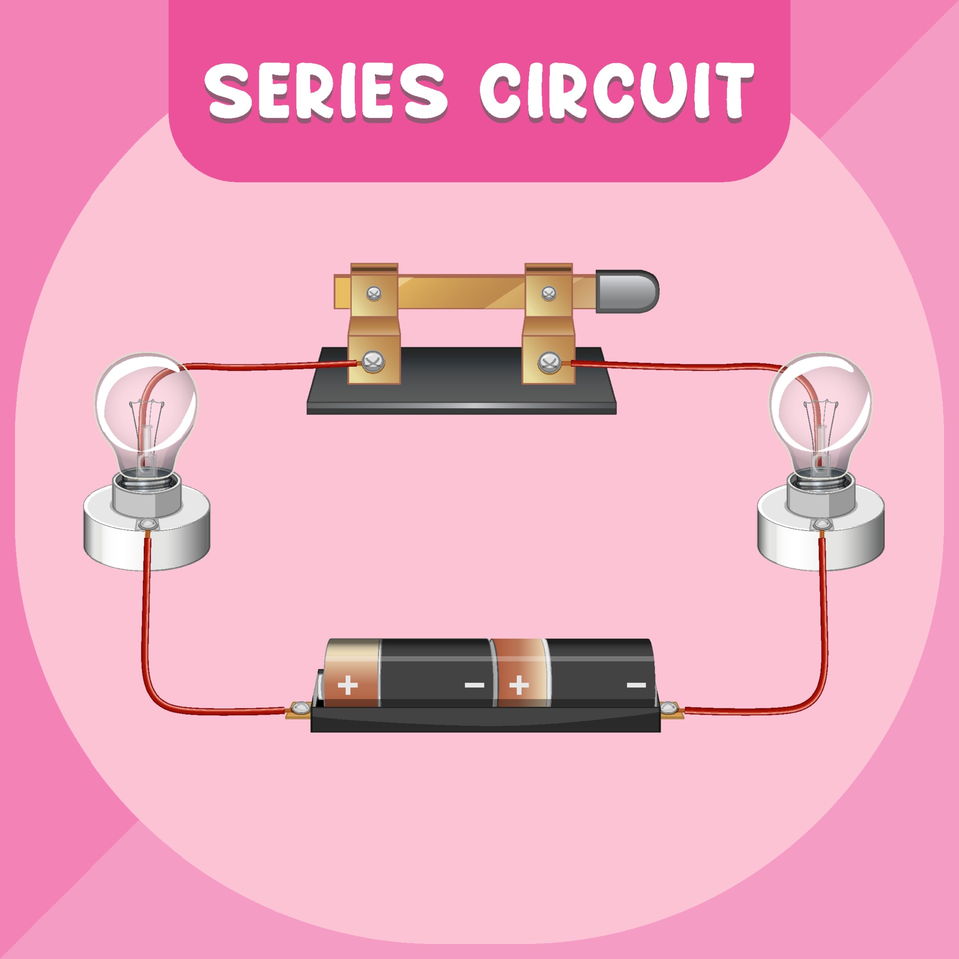
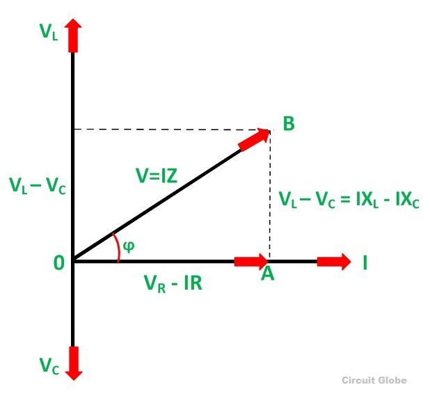
Waveform and power curve of the rc series circuit. So, the current flowing in all the elements are same i.e i r = i l = i c = i. This physics tutorial explains how to draw a series circuit made up of a lamp and. Web for drawing the phasor diagram of series rlc circuit, follow these steps: Increases when components, for example a. Now pick three spots along the wire. In a series circuit, each device is connected in a manner. 1.6m views 7 years ago. Steps to draw a phasor diagram. Resistors are like in a sequence.
A series rlc circuit containing a resistance of 12ω, an inductance of 0.15h and a capacitor of 100uf are connected in series across a 100v, 50hz supply. Web a series circuit is the simplest type of circuit: Steps to draw a phasor diagram. Students begin to make sense of the phenomenon of electricity through learning about circuits. Students use the disciplinary core idea of using evidence to construct an explanation as they learn that charge movement through a circuit depends on the resistance and arrangement of the circuit components. 1.6m views 7 years ago. Calculate the total circuit impedance, the circuits current, power factor and draw the voltage phasor diagram. Electrical circuits can be connected in. Physics circuits complex resistor combinations. Discover how voltage remains constant between elements and how current remains constant throughout the circuit.

Draw Series And Parallel Resistance Circuit Circuit Diagram
The following steps are used to draw the phasor diagram of rc series circuit. Power in rc series circuit. Record the readings on the ammeter and voltmeter in the table. Power source (battery or power supply) conductive wires. A simple series circuit with five resistors.

Parts Of A Simple Circuit
A series rlc circuit containing a resistance of 12ω, an inductance of 0.15h and a capacitor of 100uf are connected in series across a 100v, 50hz supply. Discover how voltage remains constant between elements and how current remains constant throughout the circuit. Web draw the circuit diagram for the circuit, being sure to draw an arrow indicating the direction of.
Series circuit infographic diagram 3093702 Vector Art at Vecteezy
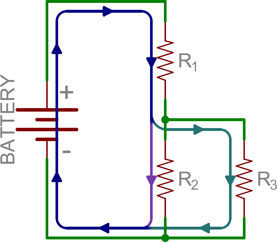
A series circuit in which the resistance is combined through the equation, rtotal = r1 + r2 +r3 +. From there we can mix and match. Web for drawing the phasor diagram of series rlc circuit, follow these steps: Web a series circuit is the simplest type of circuit: In case of series rlc circuit;
How To Get Voltage In A Series Circuit Wiring Diagram
The following steps are used to draw the phasor diagram of rc series circuit. Web explore the fundamentals of circuits and ohm's law with a focus on series circuits. A series rlc circuit containing a resistance of 12ω, an inductance of 0.15h and a capacitor of 100uf are connected in series across a 100v, 50hz supply. What series and parallel.
Example Of Series Circuit Diagram
Waveform and power curve of the rc series circuit. R1,r2,r3,.,rn is the resistance of resistors 1,2,3,.,n. A gcse revision video designed to help you learn about how to draw circuits and components, understand. The current through the circuit can be found from ohm’s law and is equal to the voltage divided by the equivalent resistance. The phasor diagram of the.
Series and Parallel Circuits
Web draw the circuit diagram for the circuit, being sure to draw an arrow indicating the direction of the current. The total voltage drop in a series circuit equals the sum. Series and parallel circuits working together. Without changing the settings, allow the simulation to run for 20 s while you count the number of electrons passing through that spot..

Series Parallel Circuit Example Problems With Solutions Wiring Draw
94k views 6 years ago gcse electricity. Web we’ll then explore what happens in series and parallel circuits when you combine different types of components, such as capacitors and inductors. Power in rc series circuit. As mentioned in the previous section of lesson 4, two or more electrical devices in a circuit can be connected by series connections or by.
What is RLC Series Circuit? Phasor Diagram & Impedance Triangle
It contains plenty of examples, equations, and formulas showing you how to solve it with all of. Web we’ll then explore what happens in series and parallel circuits when you combine different types of components, such as capacitors and inductors. Now pick three spots along the wire. This physics video tutorial explains series and parallel circuits. Increases when components, for.

Draw A Schematic Diagram Of Series And Parallel Circuit Using The Given
Without changing the settings, allow the simulation to run for 20 s while you count the number of electrons passing through that spot. In case of series rlc circuit; Resistor, capacitor and inductor are connected in series; A series rlc circuit containing a resistance of 12ω, an inductance of 0.15h and a capacitor of 100uf are connected in series across.
[Solved] Part 2 Draw a diagram of the following circuits. 8. Draw a
Web two types of connections. Increases when components, for example a. Series and parallel circuits working together. Power source (battery or power supply) conductive wires. The total resistance of a series circuit is equal to the sum of the individual resistances.
R1,R2,R3,.,Rn Is The Resistance Of Resistors 1,2,3,.,N.
Web we’ll then explore what happens in series and parallel circuits when you combine different types of components, such as capacitors and inductors. Without changing the settings, allow the simulation to run for 20 s while you count the number of electrons passing through that spot. When all the devices are connected using series connections, the circuit is referred to as a series circuit. Waveform and power curve of the rc series circuit.
Electrical Circuits Can Be Connected In.
Web construct a series circuit with 1 cell, a resistor and the ammeter in series. 1.6m views 7 years ago. In a series circuit, each device is connected in a manner. A series circuit in which the resistance is combined through the equation, rtotal = r1 + r2 +r3 +.
This Physics Tutorial Explains How To Draw A Series Circuit Made Up Of A Lamp And.
Students begin to make sense of the phenomenon of electricity through learning about circuits. As mentioned in the previous section of lesson 4, two or more electrical devices in a circuit can be connected by series connections or by parallel connections. Thus far, this unit of the physics classroom tutorial has focused on the key ingredients of an electric circuit and upon the concepts of electric. Web for drawing the phasor diagram of series rlc circuit, follow these steps:
Learn How Resistors In Series Increase Total Resistance, And How To Calculate Current Using Ohm's Law.
In the next picture, we again see three resistors and a battery. Discover how voltage remains constant between elements and how current remains constant throughout the circuit. Export circuits as scalable vector images, or convert to a selection of other formats. Web series rlc circuit example no1.