How To Draw Nyquist Plot
How To Draw Nyquist Plot - Locate the poles and zeros of open loop transfer function $g(s)h(s)$ in ‘s’ plane. Steps to draw nyquist plot here, nyquist plot includes three major steps 1. It is drawn by plotting the complex gain g(iw) for all frequencies w. Web for example, the following matlab commands produce figure \(\pageindex{1}\), a nyquist plot of equation \(\ref{eqn:10.7}\) for undamped natural frequency \(\omega_{n} = 2\pi\) rad/s and damping ratio \(\zeta=0.2\): Nyquist(sys) creates a nyquist plot of the frequency response of a dynamic system model sys. In particular, focus on the crossings of the real and imaginary axis, say the phases 0 ∘, 90 ∘, 180 ∘, 270 ∘, etc. Web in general each example has five sections: Draw the polar plot by varying $\omega$ from zero to infinity. If pole or zero present at s = 0, then varying $\omega$ from 0+ to infinity for drawing polar plot. Web 4.8k views 3 years ago nyquist stability criterion.
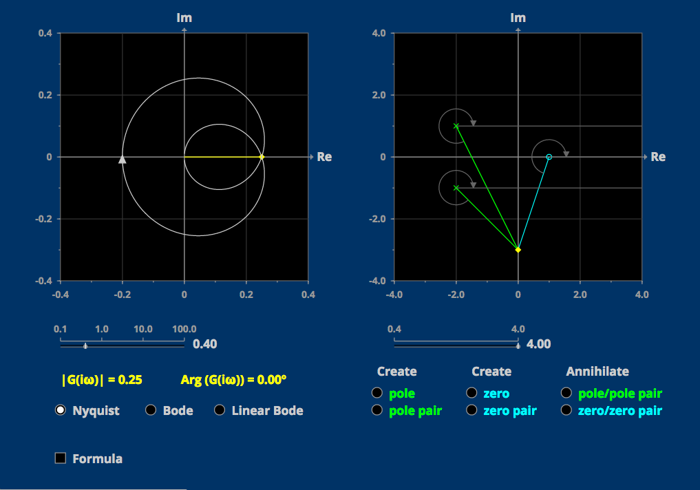
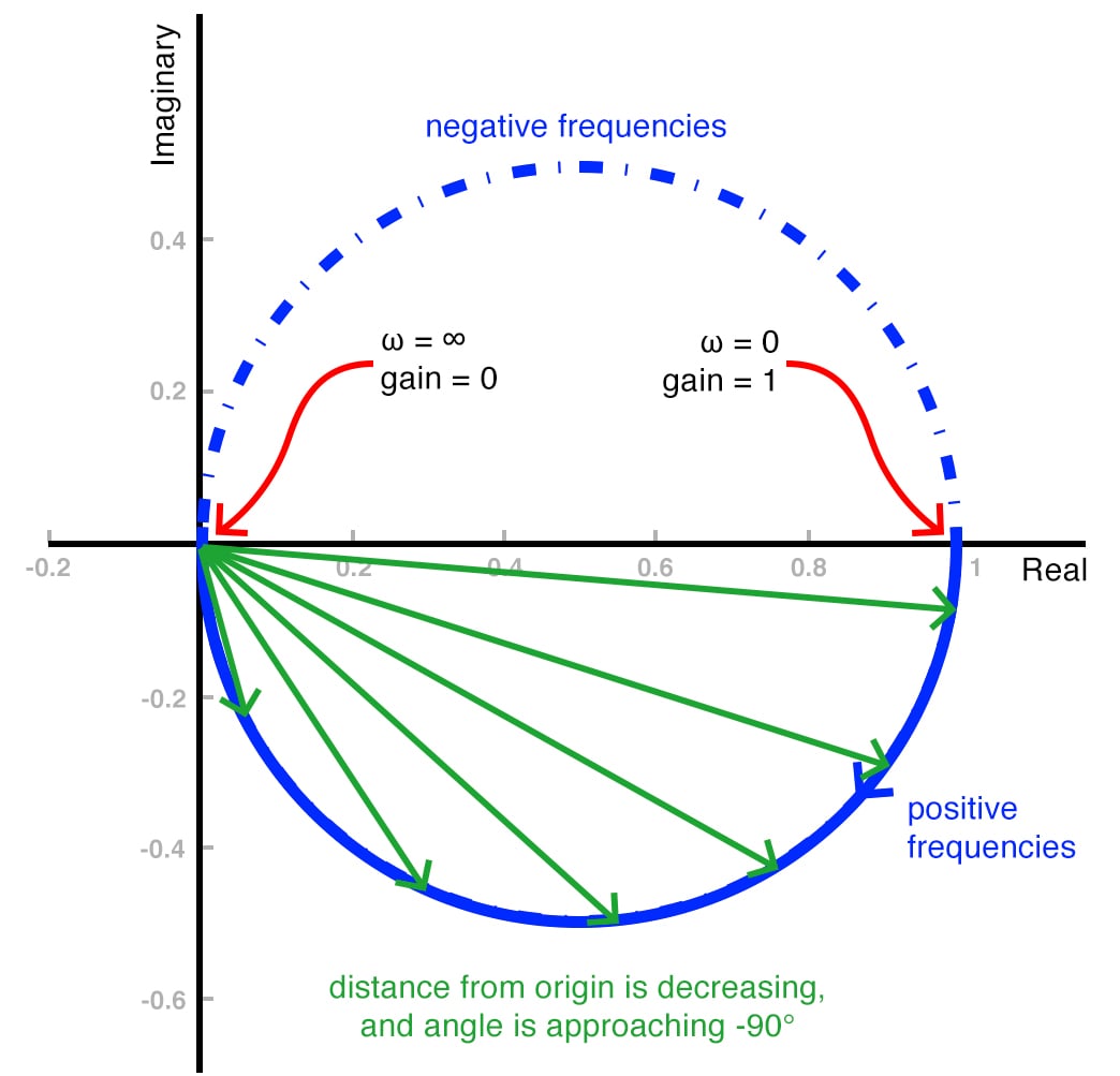
The system or transfer function determines the frequency response of a system, which can be visualized using bode plots and nyquist plots. Web 4.8k views 3 years ago nyquist stability criterion. Follow these rules for plotting the nyquist plots. Web there are two bode plots one for gain (or magnitude) and one for phase. Web the nyquist plot of a transfer function g(s) is shown in figure 1. Learn about each method, including their strengths, and why you may choose one over another. The nichols chart, the nyquist plot, and the bode plot. The nyquist plot combines gain and phase into one plot in the complex plane. Draw the polar plot by varying $\omega$ from zero to infinity. Hence, should i replace ω ω in the imaginary part with the real part, i.e., im(ω) = −re(ω) × rc 1 + (re(ω)rc)2 i m ( ω) = − r e ( ω) × r c 1 + ( r e ( ω) r c) 2.
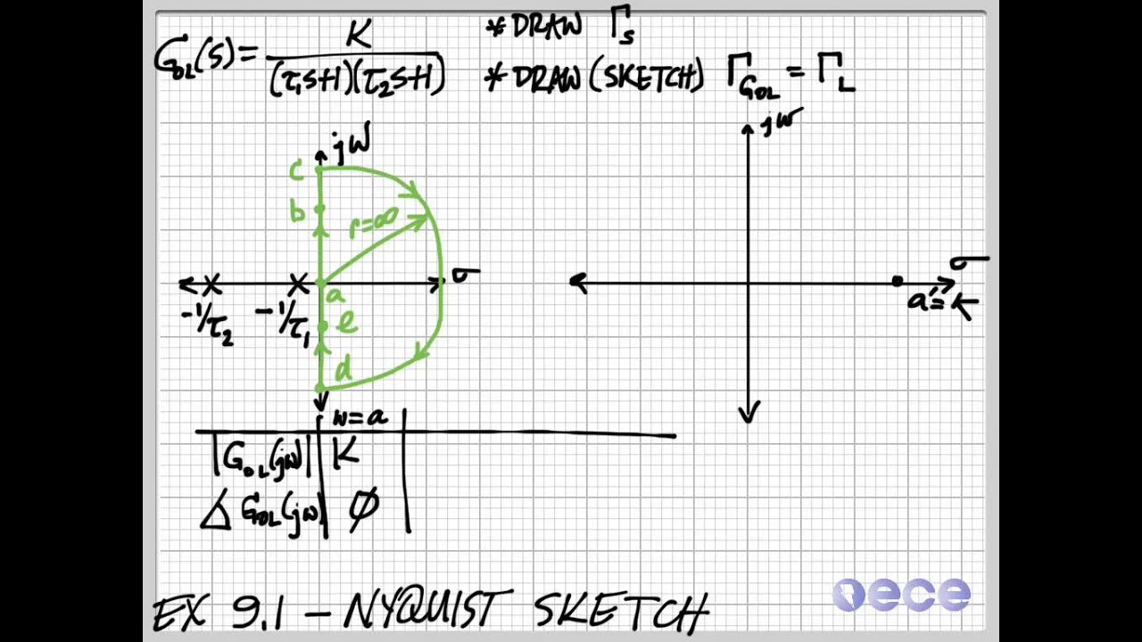
Explore math with our beautiful, free online graphing calculator. Web nyquist plot i given a plant with transfer function g(s) i want to nd the range of proportional controller (k) that would make the closed loop system stable i evaluate g(s) on every point of c 1 that encloses the entire right half plane i plot im g(s) vs. The amplitude response curves given above are examples of the bode gain plot. • l19e112 control systems lecture 19 ex. Learn about each method, including their strengths, and why you may choose one over another. Web a generic example of how to sketch a nyquist plot from a transfer functions. Using the bode plot what happens at r = 1 poles on the imaginary axis. The nichols chart, the nyquist plot, and the bode plot. Nyquist(sys) creates a nyquist plot of the frequency response of a dynamic system model sys. (a) suppose g has two unstable open loop poles.
Drawing Nyquist Plot at Explore collection of
Locate the poles and zeros of open loop transfer function $g(s)h(s)$ in ‘s’ plane. In particular, focus on the crossings of the real and imaginary axis, say the phases 0 ∘, 90 ∘, 180 ∘, 270 ∘, etc. Web steps to draw nyquist plot 3. Nyquist(sys) creates a nyquist plot of the frequency response of a dynamic system model sys..

How to draw the Nyquist plot Example No. 1 for TypeZero System
Draw the polar plot by varying $\omega$ from zero to infinity. Web how to draw nyquist plot. Phase margin and gain margin. Now i want to go into the details of how to draw one without using a bode plot. The system or transfer function determines the frequency response of a system, which can be visualized using bode plots and.
Drawing Nyquist Plot at Explore collection of
Web 1 1 + (ωrc)2 1 1 + ( ω r c) 2. The nichols chart, the nyquist plot, and the bode plot. When g(s) is placed in a unity feedback loop, is the closed loop system stable or unstable? Web for example, the following matlab commands produce figure \(\pageindex{1}\), a nyquist plot of equation \(\ref{eqn:10.7}\) for undamped natural frequency.

How to draw the Nyquist plot Example No. 2 for TypeOne System Simple
How to draw nyquist plots exercise 112: Explore math with our beautiful, free online graphing calculator. Calculate the complex transfer function value by putting s= j ω, where ‘ ω’ is angular frequency and ‘j’ is the imaginary unit. The nyquist plot combines gain and phase into one plot in the complex plane. The nichols chart, the nyquist plot, and.

How To Draw A Nyquist Diagram » Grantfire
Steps to draw nyquist plot here, nyquist plot includes three major steps 1. Draw the polar plot by varying $\omega$ from zero to infinity. Draw and map using nyquist contour. Web nyquist plot 1. Using the bode plot what happens at r = 1 poles on the imaginary axis.

How To Draw Nyquist Plot Warexamination15
Graph functions, plot points, visualize algebraic equations, add sliders, animate graphs, and more. Nyquist plot example here, nyquist plot example includes three major steps 1. Web how to draw nyquist plot? Learn about each method, including their strengths, and why you may choose one over another. Hence, should i replace ω ω in the imaginary part with the real part,.
How to Use a Nyquist Plot for AC Analysis Technical Articles
Web how to draw nyquist plot? In this lecture, you will learn: 81k views 3 years ago control systems in practice. 1) a definition of the loop gain, 2) a nyquist plot made by the nyquistgui program, 3) a nyquist plot made by matlab, 4) a discussion of the plots and system stability, and 5) a video of the output.
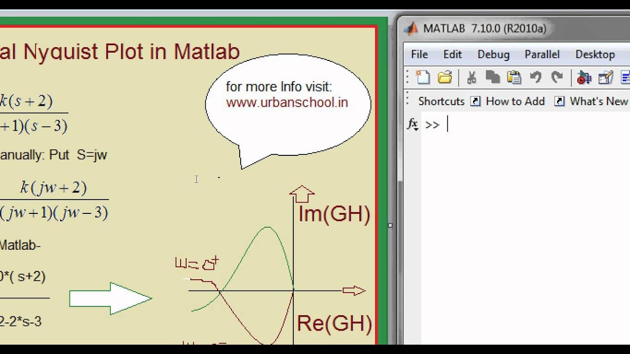
Matlab Basics Tutorial13 How to draw Nyquist plot of Transfer
Determine the transfer function of the system. Draw inverse polar plot 3. Recently i wrote a post on stability of linear systems where i introduced the nyquist plot. The nyquist plot combines gain and phase into one plot in the complex plane. Web there are two bode plots one for gain (or magnitude) and one for phase.

Control Systems Tutorial Sketch Nyquist Plots of Transfer Function by
Web nyquist diagram | desmos. Hence, should i replace ω ω in the imaginary part with the real part, i.e., im(ω) = −re(ω) × rc 1 + (re(ω)rc)2 i m ( ω) = − r e ( ω) × r c 1 + ( r e ( ω) r c) 2. Web the key for sketching the nyquist plot is.
How To Draw Nyquist Plot Warexamination15
A nyquist plot can be drawn using the following steps: Web how to draw nyquist plot. That is, the plot is a curve in the plane. How to draw nyquist plots exercise 112: Hence, should i replace ω ω in the imaginary part with the real part, i.e., im(ω) = −re(ω) × rc 1 + (re(ω)rc)2 i m ( ω).
Nyquist(Sys) Creates A Nyquist Plot Of The Frequency Response Of A Dynamic System Model Sys.
Follow these rules for plotting the nyquist plots. Phase margin and gain margin. (a) suppose g has two unstable open loop poles. Using the bode plot what happens at r = 1 poles on the imaginary axis.
Steps To Draw Nyquist Plot Here, Nyquist Plot Includes Three Major Steps 1.
If pole or zero present at s = 0, then varying $\omega$ from 0+ to infinity for drawing polar plot. Web 4.8k views 3 years ago nyquist stability criterion. Web nyquist plot 1. Graph functions, plot points, visualize algebraic equations, add sliders, animate graphs, and more.
Re G(S) In A New Plane, Call It C 4 I For Closed Loop Stability, C 4 Should Encircle ( 1=K;0), P Times I.
Recently i wrote a post on stability of linear systems where i introduced the nyquist plot. The system or transfer function determines the frequency response of a system, which can be visualized using bode plots and nyquist plots. Web nyquist plot i given a plant with transfer function g(s) i want to nd the range of proportional controller (k) that would make the closed loop system stable i evaluate g(s) on every point of c 1 that encloses the entire right half plane i plot im g(s) vs. Web how to draw nyquist plot.
Explore Math With Our Beautiful, Free Online Graphing Calculator.
The nichols chart, the nyquist plot, and the bode plot. Draw and map using nyquist contour. Nyquist contour engineering funda channel. 1) a definition of the loop gain, 2) a nyquist plot made by the nyquistgui program, 3) a nyquist plot made by matlab, 4) a discussion of the plots and system stability, and 5) a video of the output of the nyquistgui program.