How To Draw Shear Force Diagram And Bending Moment Diagram
How To Draw Shear Force Diagram And Bending Moment Diagram - Let us consider ∑m a = 0. 3m ei d 2m ei figure 1 30 kn/m v ↓ 6m 2ei 4m,2ei e of shear force diagram. Draw a horizontal line to represent the beam and divide the line by putting points at the following locations: Web ultimate guide to shear force and bending moment diagrams. 172k views 5 years ago civil engineering/structural engineering. Find the ax, ay and by values i actually need a fbd diagram before the graphs. Web the first step in calculating these quantities and their spatial variation consists of constructing shear and bending moment diagrams, \(v(x)\) and \(m(x)\), which are the internal shearing forces and bending moments induced in. So could please provide me a fbd of this beam. Web shear force and bending moment diagrams are analytical tools used in conjunction with structural analysis to help perform structural design by determining the value of shear forces and bending moments at a given point of a structural element such as a beam. Draw a fbd of the structure.
And all ☑ 80kn.m 4m ет 5m, 2et כם! Web ultimate guide to shear force and bending moment diagrams. Draw the shear force and bending moment diagrams for the loaded beam shown below. Draw a fbd of the structure. Web all throughout your civil engineering degree, you'll be asked to draw shear force and bending moment diagrams. Calculate the reactions using the equilibrium equations (may not need to do this if choosing a cantilever beam and using the free side for the fbd). This is a graphical representation of the variation of the bending moment on a segment or the entire length of a beam or frame. Simply supported beam with point load example. Write answers in the space provided below workings attached. We go through breaking a beam into.
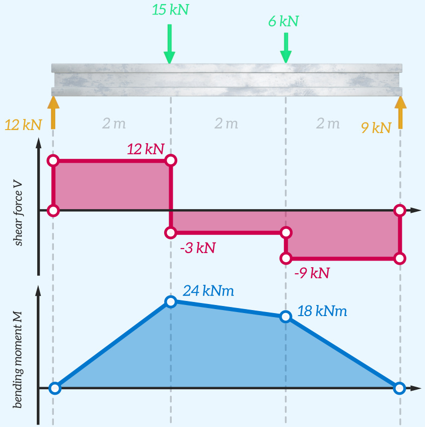
Web shear and moment diagrams are graphs which show the internal shear and bending moment plotted along the length of the beam. I do not know how to implement the force of 15 kn 3m ei d 2m ei figure 1 30 kn/m v ↓ 6m 2ei 4m,2ei e of shear force diagram. Web about press copyright contact us creators advertise developers terms privacy policy & safety how youtube works test new features nfl sunday ticket press copyright. They allow us to see where the maximum loads occur so that we can optimize the design to prevent failures and reduce the overall weight and cost of the structure. Shear force and bending moment values are calculated at supports and at points where load varies. And after that, the above example should look like below: Knowing forces effect on beams. Calculate the reactions using the equilibrium equations (may not need to do this if choosing a cantilever beam and using the free side for the fbd). Once you have the reactions, draw your free body diagram and shear force diagram underneath the beam.

Shear force and bending moment diagram practice problem 3 YouTube
Add supports (two supports for simply supported, single fixed support for cantilever) apply forces (or toggle on self weight) run calculate which will generate the bending moment diagram of the beam: Web ultimate guide to shear force and bending moment diagrams. Most structural designs relay on. Shear force and bending moment values are calculated at supports and at points where.
Solved Draw the shearforce and bendingmoment diagrams for
Find the ax, ay and by values i actually need a fbd diagram before the graphs. There is a long way and a quick way to do them. And after that, the above example should look like below: Then, we will compare the experimental values to the theoretical ones. Web shear force and bending moment diagrams are powerful graphical methods.

Solved Draw The Shearforce And Bendingmoment Diagrams F...
There is a long way and a quick way to do them. Find the ax, ay and by values i actually need a fbd diagram before the graphs. Knowing forces effect on beams. Web about press copyright contact us creators advertise developers terms privacy policy & safety how youtube works test new features nfl sunday ticket press copyright. Web the.
What is Shear Force Diagram and Bending Moment Diagram Civil
Knowing forces effect on beams. Web all throughout your civil engineering degree, you'll be asked to draw shear force and bending moment diagrams. Most structural designs relay on. Web draw the shear force, axial force and bending moment diagrams. Calculate the reaction forces by using the following basic equations:

Shear Force and Bending Moment Diagram Calculator
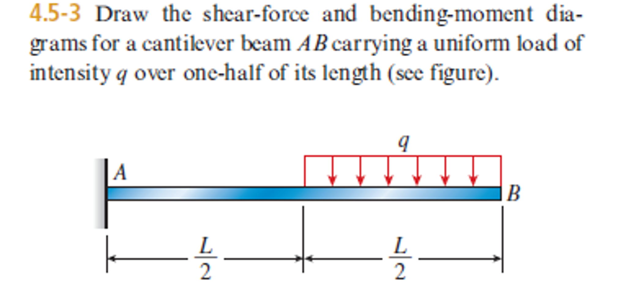
Draw the shear force and bending moment diagrams for the loaded beam shown below. This page will walk you through what shear forces and bending moments are, why they are useful, the procedure for drawing the diagrams and some other keys aspects as well. So could please provide me a fbd of this beam. Finally calculating the moments can be.
Understanding Shear Force and Bending Moment Diagrams The Efficient
And all ☑ 80kn.m 4m ет 5m, 2et כם! In this experiment, we will work on drawing the shear and bending diagram of a beam. Below a force of 10n is exerted at point a on a beam. Knowing forces effect on beams. Web this is a tutorial to make shear force diagram and bending moment diagram easily for a.

Learn How To Draw Shear Force And Bending Moment Diagrams Engineering
They allow us to see where the maximum loads occur so that we can optimize the design to prevent failures and reduce the overall weight and cost of the structure. Draw the shear force and bending moment diagrams for the loaded beam shown below. 1 what is shear force? Web shear force and bending moment diagrams are powerful graphical methods.

Learn How To Draw Shear Force And Bending Moment Diagrams Engineering
Most structural designs relay on. Beam is simply supported ∑m a = ∑m c = 0. Using the machine in figure 1, we will measure the shear force and bending moment of a beam after subjecting it to given loads. In this experiment, we will work on drawing the shear and bending diagram of a beam. Web this is a.

Shear force & Bending Moment Formulas With Diagram CCAL Shear force
Below a force of 10n is exerted at point a on a beam. Web all throughout your civil engineering degree, you'll be asked to draw shear force and bending moment diagrams. 3m ei d 2m ei figure 1 30 kn/m v ↓ 6m 2ei 4m,2ei e of shear force diagram. This is a graphical representation of the variation of the.
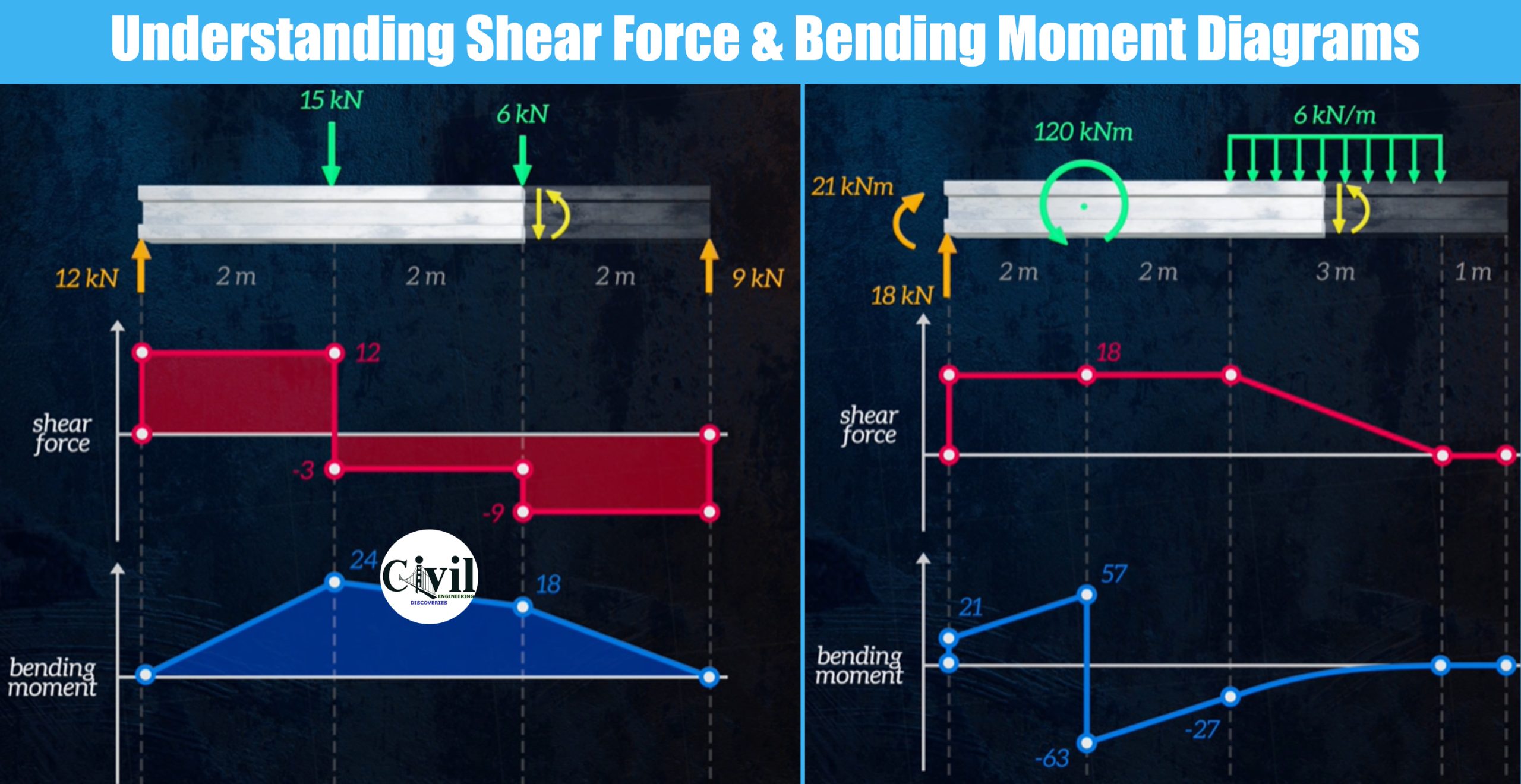
Understanding Shear Force And Bending Moment Diagrams Engineering
Web ultimate guide to shear force and bending moment diagrams. Calculate the reactions using the equilibrium equations (may not need to do this if choosing a cantilever beam and using the free side for the fbd). It is critical that all structural engineers understand how to draw bending moment and shear force diagrams. We go through breaking a beam into..
Add Supports (Two Supports For Simply Supported, Single Fixed Support For Cantilever) Apply Forces (Or Toggle On Self Weight) Run Calculate Which Will Generate The Bending Moment Diagram Of The Beam:
Web this video explains how to draw shear force diagram and bending moment diagram with easy steps for a cantilever beam loaded with a concentrated load. 22k views 3 years ago melbourne. Below a force of 10n is exerted at point a on a beam. By learning the technique shown in this video.
Knowing Forces Effect On Beams.
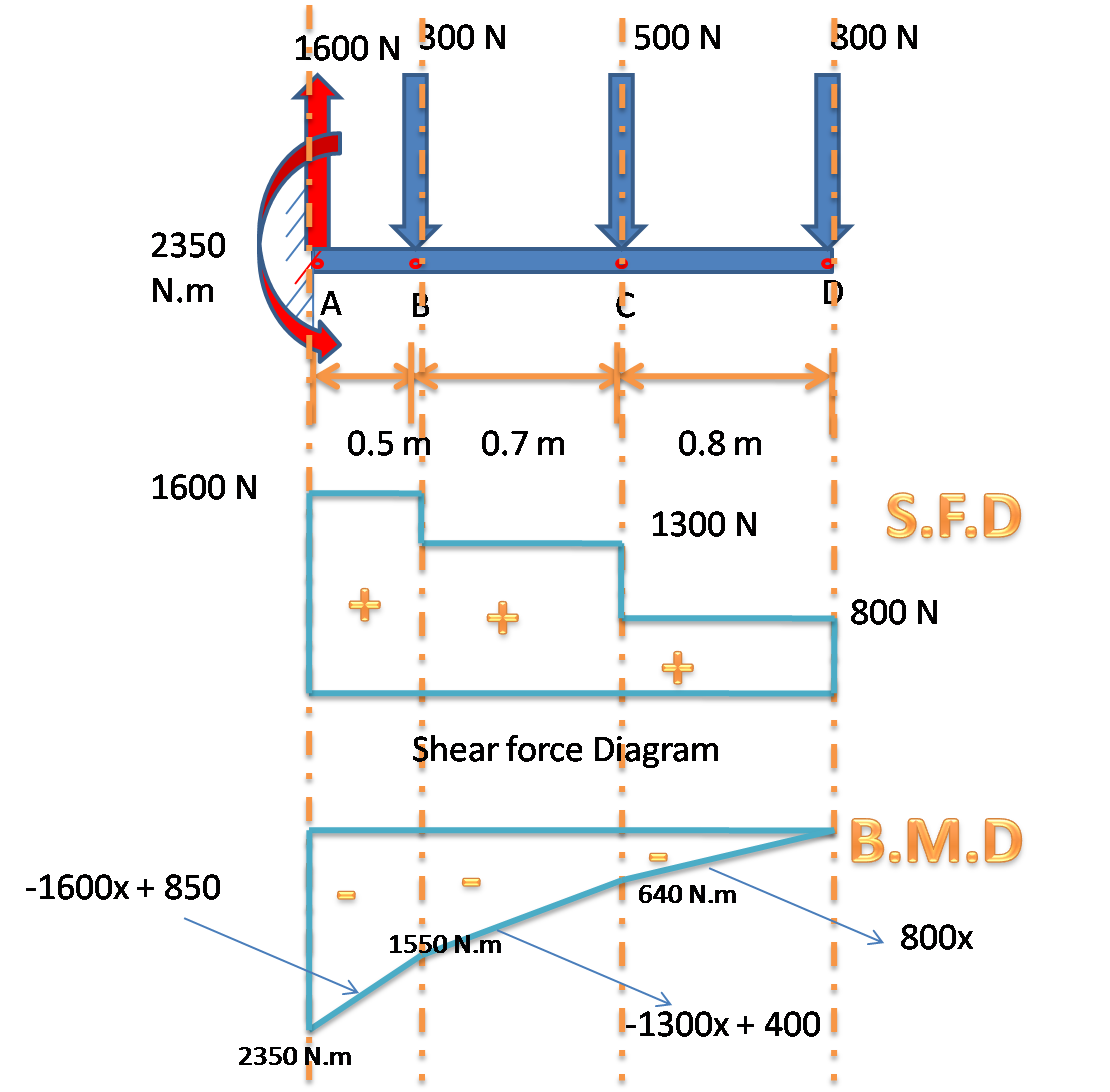
There is a long way and a quick way to do them. This is a graphical representation of the variation of the bending moment on a segment or the entire length of a beam or frame. To find out shear force, first, we will calculate r a and r c. Web shear force and bending moment diagram of simply supported beam can be drawn by first calculating value of shear force and bending moment.
3M Ei D 2M Ei Figure 1 30 Kn/M V ↓ 6M 2Ei 4M,2Ei E Of Shear Force Diagram.
1 what is shear force? Web about press copyright contact us creators advertise developers terms privacy policy & safety how youtube works test new features nfl sunday ticket press copyright. Beam is simply supported ∑m a = ∑m c = 0. To complete a shear force and bending moment diagram neatly you will need the following materials.
Once You Have The Reactions, Draw Your Free Body Diagram And Shear Force Diagram Underneath The Beam.
It is critical that all structural engineers understand how to draw bending moment and shear force diagrams. Most structural designs relay on. They allow us to see where the maximum loads occur so that we can optimize the design to prevent failures and reduce the overall weight and cost of the structure. Draw a horizontal line to represent the beam and divide the line by putting points at the following locations: