Hydraulic Schematic Drawing
Hydraulic Schematic Drawing - Web engineering drawings for hydraulics have a few symbols and practices that distinguish them from a standard engineering drawing. 295 views • 11 days ago. This pdf contains the symbols and explanations for the different types of hydraulic line as well as some basic components you may encounter when reading or creating a hydraulic circuit diagram. Welcome to digikey's free online schematic and diagramming tool. It provides a visual representation of how the system works, allowing engineers and technicians to understand and troubleshoot the system more easily. Web hydrosym is a software solution that helps you to easily and flawlessly design the schematics of any hydraulic system. Web by representing hydraulic components using symbols, engineers can create schematics that clearly depict the layout, flow paths, and interactions within a hydraulic system. 356k views 8 years ago hydraulics and electrical control of hydraulic systems. Different symbology is used when dealing with systems that operate with fluid power. Activate multiple valves at a time to see if there are unintentional consequences.
Web hydrosym is a software solution that helps you to easily and flawlessly design the schematics of any hydraulic system. One can understand a wide range of different hydraulic symbols, representing components performing similar tasks with. Select from a huge library of vector schematic diagram symbols that scale easily without quality degradation. Web the basic steps to reading a hydraulic schematic are: Web the basic steps to reading a hydraulic schematic are: When lines in a schematic represent hoses, tubes or pipes on a machine, they are often required to cross or join. Beginning at the basics all the way to advanced, we cover everything you need to know to read a hydraulic schematic. Discuss the advantages and disadvantages of representing hydraulic components using pictorial, cutaway, and schematic symbols. Hydraulic component an overview sciencedirect topics. The dwg files can open in popular cad apps, autocad/lt, and.
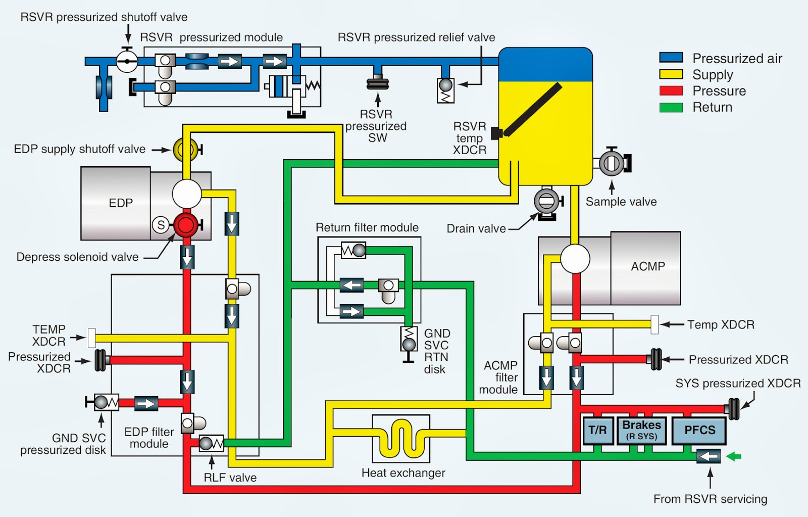
Web a schematic diagram is a representation of a hydraulic system using symbols and lines to show the various components and their connections. Web hydrosym is a software solution that helps you to easily and flawlessly design the schematics of any hydraulic system. Let’s start with the basics. One can understand a wide range of different hydraulic symbols, representing components performing similar tasks with. What do circles, semi circles, squares, rectangles, diamonds and lines represent in hydraulic schematics? Fluid power diagrams and schematics. Identify if lines cross with or without connecting. It provides a visual representation of how the system works, allowing engineers and technicians to understand and troubleshoot the system more easily. The best way to read a hydraulic schematic mentored engineer. Fluid power diagrams and schematics require an independent review because they use a unique set of symbols and conventions.

Hydraulic Circuit Diagrams
Web a schematic diagram is a representation of a hydraulic system using symbols and lines to show the various components and their connections. The likes of hydrosym, conceptdraw, fluiddraw, and smartdraw, maybe you'll be tempted to give the sun's quickdesign a try, or maybe look into the rexroth's scheme editor, or maybe some other piece of specialized software that will.
Schematic Diagram Of Hydraulic System
Activate multiple valves at a time to see if there are unintentional consequences. Web discover hydraulic lines & basic symbols. The basic drawn lines, cylinder symbols, ejector symbols, and the do not scale note are just a handful of items that are particular to engineering drawings for hydraulics. See prices get started within 15 minutes try it for free. Activate.
Hydraulic Schematic Diagram Symbols
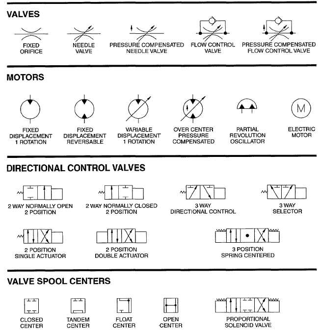
Basic symbols representing hydraulic components. Quickly design accurate hydraulic circuits with bill of materials. Discuss the advantages and disadvantages of representing hydraulic components using pictorial, cutaway, and schematic symbols. Armed with knowledge of how basic hydraulic components are represented in the hydraulic circuit; Download the fully functional free trial version here (less than 3.5 mb).

How To Draw A Hydraulic Schematic
Web hydraulic schematics (full lecture) watch on. This pdf contains the symbols and explanations for the different types of hydraulic line as well as some basic components you may encounter when reading or creating a hydraulic circuit diagram. Hydraulic component an overview sciencedirect topics. Beginning at the basics all the way to advanced, we cover everything you need to know.

Hydraulic System Schematic
As a drain line, the dashed line simply represents any component with leakage fluid needing a path represented in the drawing. Web the basic steps to reading a hydraulic schematic are: Activate multiple valves at a time to see if there are unintentional consequences. Web hydrosym is a software solution that helps you to easily and flawlessly design the schematics.
Digital hydraulic schematic diagram of working device of loader
Web a schematic diagram is a representation of a hydraulic system using symbols and lines to show the various components and their connections. Save and share hydraulic circuits as dwg file. Download the fully functional free trial version here (less than 3.5 mb). Web hydraulic schematics (full lecture) watch on. Fluid power diagrams and schematics require an independent review because.

A guide to common hydraulic symbols EngineeringClicks
Web discover hydraulic lines & basic symbols. Basic symbols representing hydraulic components. Hydraulic component an overview sciencedirect topics. The likes of hydrosym, conceptdraw, fluiddraw, and smartdraw, maybe you'll be tempted to give the sun's quickdesign a try, or maybe look into the rexroth's scheme editor, or maybe some other piece of specialized software that will come about. Save and share.

Guide to Understand Hydraulic Cylinder Parts Names & Diagram
Identify if lines cross with or without connecting. Select from a huge library of vector schematic diagram symbols that scale easily without quality degradation. Download the fully functional free trial version here (less than 3.5 mb). Quickly design accurate hydraulic circuits with bill of materials. Different symbology is used when dealing with systems that operate with fluid power.

Hydraulic Diagram PDF
Determine what happens as each valve is moved. The likes of hydrosym, conceptdraw, fluiddraw, and smartdraw, maybe you'll be tempted to give the sun's quickdesign a try, or maybe look into the rexroth's scheme editor, or maybe some other piece of specialized software that will come about. This visual representation enables quicker comprehension of system operation and aids in troubleshooting..

Simple Schematic Diagram Of Hydraulic System Switch Wiring Diagram
Discuss the advantages and disadvantages of representing hydraulic components using pictorial, cutaway, and schematic symbols. Fluid power diagrams and schematics require an independent review because they use a unique set of symbols and conventions. Differentiate between working, pilot, and drain lines and show how these lines are depicted schematically. Basic symbols representing hydraulic components. Let’s start with the basics.
This Visual Representation Enables Quicker Comprehension Of System Operation And Aids In Troubleshooting.
See prices get started within 15 minutes try it for free. Web the basic steps to reading a hydraulic schematic are: When lines in a schematic represent hoses, tubes or pipes on a machine, they are often required to cross or join. The basic drawn lines, cylinder symbols, ejector symbols, and the do not scale note are just a handful of items that are particular to engineering drawings for hydraulics.
Web Engineers Can Use This Page As A Reference To Determine Common Schematic Symbols Used In Fluid Power, Hydraulics, Pneumatics, Diagrams And Circuits.
Quickly design accurate hydraulic circuits with bill of materials. Web discover hydraulic lines & basic symbols. Web the basic steps to reading a hydraulic schematic are: How to read hydraulic circuits schematic symbols din iso 1219.
It Includes Thousands Of Templates And Examples To Help You Get Started Quickly.
Welcome to digikey's free online schematic and diagramming tool. Web by representing hydraulic components using symbols, engineers can create schematics that clearly depict the layout, flow paths, and interactions within a hydraulic system. Determine what happens as each valve is moved. Fluid power diagrams and schematics.
Determine What Happens As Each Valve Is Moved.
What do circles, semi circles, squares, rectangles, diamonds and lines represent in hydraulic schematics? Beginning at the basics all the way to advanced, we cover everything you need to know to read a hydraulic schematic. Armed with knowledge of how basic hydraulic components are represented in the hydraulic circuit; Different symbology is used when dealing with systems that operate with fluid power.