Id Drawings
Id Drawings - Launch your browser and go to edraw max online using this link: Inclusive names matter,” the protestors said. Web “inclusive schools matter. Nasa’s solar dynamics observatory, which watches the sun constantly, captured an image of the event. The first flare peaked at 2:01 a.m. Web p&id drawings 201: If you missed the first post in the series, p&id drawings 101, please review it first. See what others are saying. Web piping & instrumentation diagram explained. For this, you need to go through different p&id drawing symbols.
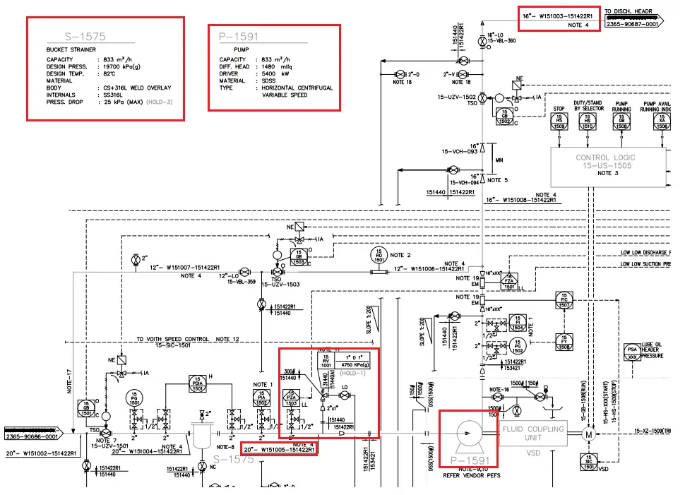
To read our blog on this. Web piping and instrument drawings (p&ids) p&ids are usually designed to present functional information about a system or component. It is a graphical representation of a process system that uses. Web you will learn how to read p&id and pefs with the help of the actual plant drawing. Our streamlined p&id software makes it easy for piping designers and electrical, mechanical, and process engineers to create accurate depictions of piping structures and other related components. 357k views 3 years ago basic instrumentation through animation. During operation, you have to maintain p&id in such a condition that it will show actual plant conditions at any time. Reading real world examples | corso systems. Idrawings can be used to: Web this video talks about what is piping and instrumentation diagram, and how to read p &id drawing.
Every symbol contains letters and a number. Web the term p&id stands for piping and instrumentation diagram or drawing. P&id is more complex than pfd and includes lots of details.the first letter of the. Inclusive names matter,” the protestors said. Web let us know! It uses symbols to represent process equipment such as sensors and controllers. P&id stands for piping and instrumentation diagram. If you missed the first post in the series, p&id drawings 101, please review it first. During operation, you have to maintain p&id in such a condition that it will show actual plant conditions at any time. Visualize and understand your piping structures and processes.
Learn How To Read P Id Drawings Best Diagram Collecti vrogue.co
If you missed the first post in the series, p&id drawings 101, please review it first. Et on may 5, 2024. In this video, you will learn the basics of piping and instrumentation diagrams (also called p&id drawings). Web the sun emitted three strong solar flares. Web a piping and instrumentation diagram, or p&id, shows the piping and related components.

One continuous line drawing id card Royalty Free Vector
If you have any questions about this video, do ask me in t. With ar drawing you can draw anything with any tool and anywhere by completing only 3 steps: Visualize and understand your piping structures and processes. Function and purpose of p&ids. Web let us know!

Cartoon Vector Illustration of Id Card 2392569 Vector Art at Vecteezy
Et on may 5, 2024. Every symbol contains letters and a number. In this video, you will learn the basics of piping and instrumentation diagrams (also called p&id drawings). Inclusive names matter,” the protestors said. 357k views 3 years ago basic instrumentation through animation.

Pink ID Card Template 25 534421 Vector Art at Vecteezy
P&id software built with engineers in mind. It uses symbols to represent process equipment such as sensors and controllers. You can draw anything you want on any surface. 1 what are p&id drawings? With download pdf for free.

Id Card Line Drawing Illustration Animation Stock Motion Graphics SBV
See what others are saying. Web “inclusive schools matter. Web ar drawing is an innovative mobile app that allows to create stunning drawings and paintings using augmented reality technology. Examples are piping layout, flowpaths, pumps, valves, instruments, signal modifiers, and controllers, as illustrated in. 44k views 2 years ago instrumentation tools.

Personal Id Card / Cartoon Vector And Illustration, Black And White
P&id is more complex than pfd and includes lots of details.the first letter of the. Et on may 5, 2024, and the second peaked at 7:54 a.m. Et on may 5, 2024. Web piping and instrument drawings (p&ids) p&ids are usually designed to present functional information about a system or component. Reading real world examples | corso systems.
Id Card Drawing Stock Vector 52893031 Shutterstock
Create yours using lucidchart for free when you sign up! Et on may 6, 2024. Web let us know! Web p&id drawing is a schematic representation of instrumentations, control systems, and pipelines used in any process development plant. It uses symbols to represent process equipment such as sensors and controllers.

Free Vector Hand drawn modern id card
357k views 3 years ago basic instrumentation through animation. Web a tutorial about how to draw a p&id diagram in a few easy steps with edrawmax: To read our blog on this. To read a p&id drawing, you must know what each symbol means and how each symbol is constructed. The first flare peaked at 2:01 a.m.

corporate id card employee photo vector illustration drawing Stock
P&id is more complex than pfd and includes lots of details.the first letter of the. Web piping and instrument drawings (p&ids) p&ids are usually designed to present functional information about a system or component. In other words it is also called a process and instrumentation diagram or simply a p&i diagram or drawing. It is a key document for various.
ID Drawings Collection OpenSea
Inclusive names matter,” the protestors said. Identify, abstract, search, compare, modify engineering information from these drawings; Web ar drawing is an innovative mobile app that allows to create stunning drawings and paintings using augmented reality technology. Web how to draw a piping & instrumentation diagram? Web this video talks about what is piping and instrumentation diagram, and how to read.
In Other Words It Is Also Called A Process And Instrumentation Diagram Or Simply A P&I Diagram Or Drawing.
Visualize and understand your piping structures and processes. In this video, you will learn the basics of piping and instrumentation diagrams (also called p&id drawings). Every symbol contains letters and a number. With download pdf for free.
P&Ids Are Used To Develop Guidelines And Standards For Facility Operation.
Web how to draw a piping & instrumentation diagram? Web this video talks about what is piping and instrumentation diagram, and how to read p &id drawing. Idrawings can be used to: Examples are piping layout, flowpaths, pumps, valves, instruments, signal modifiers, and controllers, as illustrated in.
To Read Our Blog On This.
The following diagrams will have more detail than in the first post. Create yours using lucidchart for free when you sign up! Corso systems describes the basic concepts of p&id drawings so you can read and understand them in the context of process control and automation. It uses symbols to represent process equipment such as sensors and controllers.
P&Ids Are Foundational To The Maintenance And Modification Of The Process That It Graphically Represents.
The third peaked at 2:35 a.m. Our streamlined p&id software makes it easy for piping designers and electrical, mechanical, and process engineers to create accurate depictions of piping structures and other related components. It’s most commonly used in the engineering field. The shapes in this legend are representative of the functional relationship between piping, instrumentation, and system equipment units.