Industrial Drawing Symbols
Industrial Drawing Symbols - Drawing views are simply the representation of your component from multiple. Various symbols are used to indicate piping components, instrumentation, equipments in engineering drawings such as piping and instrumentation diagram (p&id), isometric drawings, plot plan, equipment layout, welding drawings etc. Web cad systems will have symbol libraries from which the user can select the symbols relevant to their drawing. Checkout list of such symbols given below. Angular units are important also but there is. Web engineering drawing abbreviations and symbols are used to communicate and detail the characteristics of an engineering drawing. Users reported that in inventor drawing, moving text notes with symbol annotation (like sketch symbols or surface symbols) is inconsistent. After selecting many elements at once, all drawing annotations will move together. Web the basic drawing standards and conventions are the same regardless of what design tool you use to make the drawings. If the drawing is made without either instruments or cad, it is called a freehand sketch.
The first tool in your engineering drawing toolbox is the drawing view. Web the stock nvda, +0.58% slipped 0.3% in morning trading monday, to erase an earlier intraday gain of as much as 1.1%. Views, dimensions, tolerances, symbols, datum’s, feature control frames & title blocks. Web the best way to learn gd&t is from experienced teachers who can break down the material into manageable pieces. To make the drawings easier to understand, people use familiar symbols, perspectives, units of. If the drawing is made without either instruments or cad, it is called a freehand sketch. Drawing views are simply the representation of your component from multiple. Conceptdraw diagram users have access to all of them and can insert them into the drawing by simply dragging and dropping: The true position theory and the specification of tolerance zones are also explained. They are 1) piping and instrument drawings (p&ids), 2) electrical single lines and schematics, 3) electronic diagrams and schematics, 4) logic diagrams and prints, and 5) fabrication, construction, and architectural drawings.
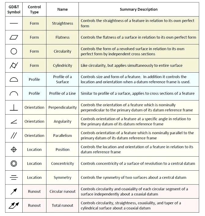
Web this page explains the 16 symbols used in gd&t, and the classification thereof. Web example of diagram reading. A radius dimension is preceded by an `r´. The true position theory and the specification of tolerance zones are also explained. Web one of the first steps in learning to read machine drawings is to become familiar with key terms, symbols, and conventions in general use in the industry. “learning gd&t from scratch,” provided by keyence, walks you through the basics of geometric dimensioning and tolerancing, datums, and measurements by coordinate measuring. They are a good visual representation of the desired item,. Checkout list of such symbols given below. Web the stock nvda, +0.58% slipped 0.3% in morning trading monday, to erase an earlier intraday gain of as much as 1.1%. A power station is an industrial facility for the generation.

Engineering Drawing Symbols And Their Meanings Pdf at PaintingValley
If you are on a site, the most. A radius dimension is preceded by an `r´. A power station is an industrial facility for the generation. Views, dimensions, tolerances, symbols, datum’s, feature control frames & title blocks. Checkout list of such symbols given below.
Engineering Symbols Chart A Visual Reference of Charts Chart Master
Now let’s go back to industrial diagrams, primarily focusing on schematic diagrams.a site electrician, for each system and distribution cabinet, has a set of plans in a3 and/or a4 format with ‘n’ sheets representing the installation “sequential” in control (or command) diagram and power diagram form. Web units of measurement. Web this chapter will introduce the five common categories of.

Standard Engineering Drawing Symbols Design Talk
Web this page explains the 16 symbols used in gd&t, and the classification thereof. After selecting many elements at once, all drawing annotations will move together. “learning gd&t from scratch,” provided by keyence, walks you through the basics of geometric dimensioning and tolerancing, datums, and measurements by coordinate measuring. Common abbreviations include ac (alternating current), dc (direct current), fab (fabrication),.

Engineering Drawing Symbols And Their Meanings Pdf at PaintingValley
Web this page explains the 16 symbols used in gd&t, and the classification thereof. Conceptdraw diagram users have access to all of them and can insert them into the drawing by simply dragging and dropping: Web the stock nvda, +0.58% slipped 0.3% in morning trading monday, to erase an earlier intraday gain of as much as 1.1%. The true position.
Engineering Drawing Symbols And Their Meanings Pdf at PaintingValley
Web ask the assistant. The letter ‘h’ represents the predominant character height on a drawing. Get the best gd&t training available. “learning gd&t from scratch,” provided by keyence, walks you through the basics of geometric dimensioning and tolerancing, datums, and measurements by coordinate measuring. Various symbols are used to indicate piping components, instrumentation, equipments in engineering drawings such as piping.

Mechanical Engineering Drawing Symbols Pdf Free Download at
Web this standards publication was prepared by a technical committee of the nema industrial automation control products and systems section. Whether cad is used in civil engineering, mechanical engineering, electrical engineering or to create escape route plans, some symbols occur repeatedly. Common abbreviations include ac (alternating current), dc (direct current), fab (fabrication), and ld (load). Various symbols are used to.

Technical Drawing Symbols
Views, dimensions, tolerances, symbols, datum’s, feature control frames & title blocks. They are a good visual representation of the desired item,. This list includes abbreviations common to the vocabulary of people who work with engineering drawings in the manufacture and inspection of parts and assemblies. Web a good design drawing can indicate all the details needed to produce a mechanical.

Engineering Drawing Symbols And Their Meanings Pdf at GetDrawings
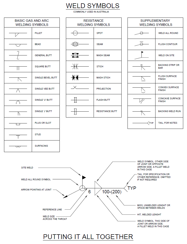
Web example of diagram reading. Web cad systems will have symbol libraries from which the user can select the symbols relevant to their drawing. A radius dimension is preceded by an `r´. Web ask the assistant. They are also used to show the fillets given to strengthen the edges at connecting faces.

Mechanical Drawing Symbols from Mechanical Engineering — Welding
Web mechanical engineering solution offers 602 commonly used mechanical drawing symbols and objects which are professionally designed and grouped in 8 libraries. Technical drawing is essential for communicating ideas in industry and engineering. It was approved in accordance with the bylaws of nema and supersedes the indicated nema standards publication. The measurement units will often be called out in the.

Mechanical Engineering Drawing Symbols Pdf Free Download at
Web a good design drawing can indicate all the details needed to produce a mechanical cnc milling part in an easy way. Technical standards exist to provide glossaries of. The first tool in your engineering drawing toolbox is the drawing view. Web this standards publication was prepared by a technical committee of the nema industrial automation control products and systems.
Web A Good Design Drawing Can Indicate All The Details Needed To Produce A Mechanical Cnc Milling Part In An Easy Way.
Web japan’s nikkei asia reported sunday that arm arm, +7.71% will set up an ai chip division and launch a prototype by next spring, with aims of mass production through contract manufacturers. And machinistguides.com readers get an exclusive discount on training! The letter ‘h’ represents the predominant character height on a drawing. After selecting many elements at once, all drawing annotations will move together.
If The Drawing Is Made Without Either Instruments Or Cad, It Is Called A Freehand Sketch.
In learning drafting, we will approach it from the perspective of manual drafting. Technical drawing is essential for communicating ideas in industry and engineering. Web the best way to learn gd&t is from experienced teachers who can break down the material into manageable pieces. Technical standards exist to provide glossaries of.
Web This Standards Publication Was Prepared By A Technical Committee Of The Nema Industrial Automation Control Products And Systems Section.
Views, dimensions, tolerances, symbols, datum’s, feature control frames & title blocks. Conceptdraw diagram users have access to all of them and can insert them into the drawing by simply dragging and dropping: This standards publication contains the information that was previously located in clause 9. Web these abbreviations can be found on engineering drawings such as mechanical, electrical, piping and plumbing, civil, and structural drawings.
Although Today's Cad Packages Make The Production Of Industrial Drawings Much Easier, It Is Still Imperative To Follow Industry Standards And Conventions.
Radius can be for the inside and outside curved surface on the part. The measurement units will often be called out in the title block or tolerance block but occasionally will be in another section of the blueprint such as in the notes. They are a good visual representation of the desired item,. For example, r6 means the circle has a radius of 6mm.