Isometric Drawing Of Pipe Line
Isometric Drawing Of Pipe Line - Dimension is given relative to. Construction techniques for isometric drawing. Web piping isometric is a representation of a single pipe line in a process plant with exact dimensions and bill of material (bom). These highly structured drawings provide a comprehensive 3d representation of the arrangement, dimensions, and connections of pipes within a system. Piping joint types, weld types; Web tube & pipe: No more tedious material tracking when creating a pipe isometric drawing. Web piping isometric drawing consists of three sections. This is done by drawing the lines parallel to isometric axes. Web the fitting, flange, and valve drawing symbols unique to isometrics are depicted.
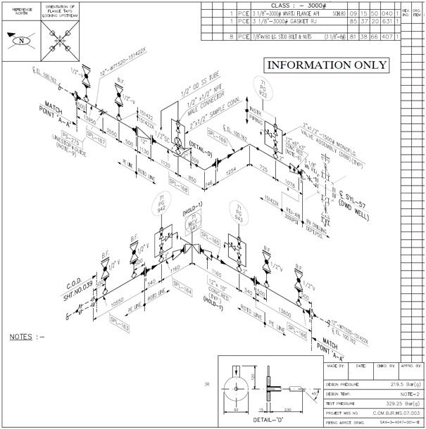
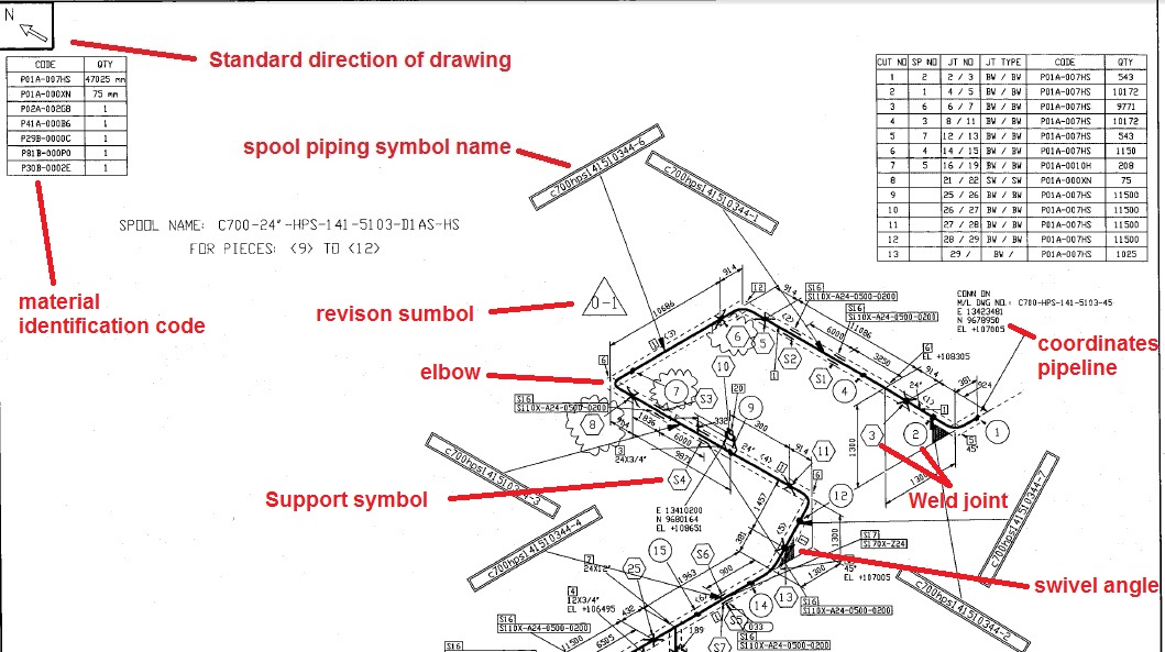
Main graphic section consist of isometric representation of a pipe line route in 3d space, which includes following information : Web the fitting, flange, and valve drawing symbols unique to isometrics are depicted. The use of coordinate and elevation callouts to determine configuration dimensions of the routed pipe is explained. Web drawing an isometric proportionally simply means drawing a 10m run of pipe twice as long as a 5m length of pipe. Web a pipe into a isometric view, is always drawn by a single line. Work from hand sketches or just draw them directly. It is the most important deliverable of any project where piping plays a vital role. We are concluding our first pipefitter series run with a video on how to draw isometric drawings. Piping and component descriptions with size, quantity, and material codes Isometric drawings are typically used to show the details of a piping system, such as the size and type of piping, the direction of flow of the fluids, and the location of valves, pumps, and other equipment nozzles.
Web a piping isometric drawing is a simplified representation of a pipeline system. Web piping isometric is a representation of a single pipe line in a process plant with exact dimensions and bill of material (bom). Generating isometrics | autodesk virtual academy. In the world of industrial projects, precision and accuracy are of utmost importance. It is quite easy creating isometric lines on isometric planes. They serve as precise illustrations providing essential information about the layout, dimensions, materials, and key components of a pipeline system. Web the fitting, flange, and valve drawing symbols unique to isometrics are depicted. It’s popular within the process piping industry because it can be laid out and drawn with ease and portrays the. Web piping isometric drawing consists of three sections. As you draw, the bom generates and updates itself automatically.

Piping Isometric Drawing at Explore collection of
Web an isometric drawing covers a complete line as per the line list and p&id. Isometrics are not drawn to scale but should be proportional to easy understanding. Web a pipe into a isometric view, is always drawn by a single line. Generating isometrics | autodesk virtual academy. It contains the dimensions of the pipeline route and the position of.
Isometric water pipe line detail dwg file Cadbull
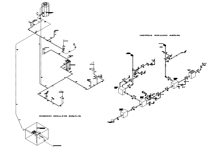
Web piping isometric is a representation of a single pipe line in a process plant with exact dimensions and bill of material (bom). The pipelines with all components and fittings are shown in a n isomertic drawing with a 30°/30° grid. Main graphic section consist of isometric representation of a pipe line route in 3d space, which includes following information.

How to read piping Isometric drawing YouTube
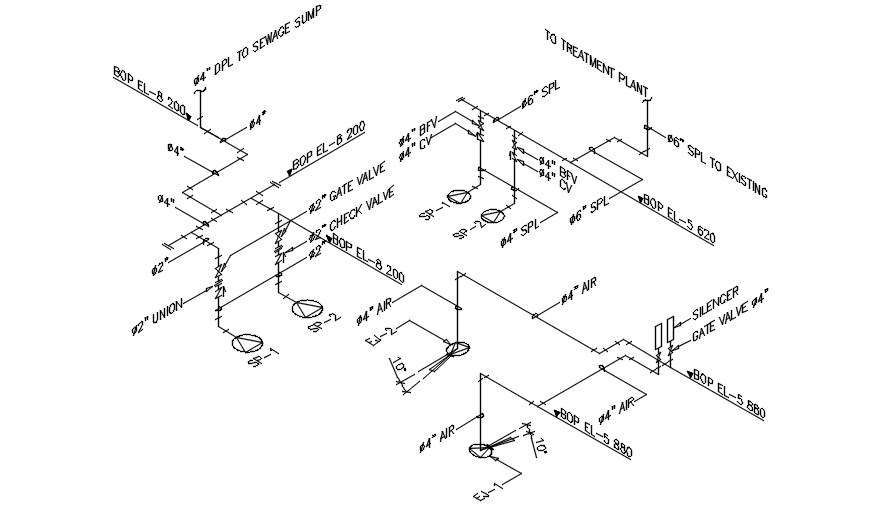
No more tedious material tracking when creating a pipe isometric drawing. Web a piping isometric drawing provides all the required information like: 254k views 2 years ago. Are drawings which shows details of process pipe lines in a single line presentation , with details of pipes, pipe connections ( valves, flanges, nipples, reducers, end cap, elbow, etc), along with the.
Isometric Pipe Line CAD Drawing Free Download DWG File Cadbull
It contains the dimensions of the pipeline route and the position of the piping components in isometric projection. 254k views 2 years ago. Generating isometrics | autodesk virtual academy. Piping and component descriptions with size, quantity, and material codes This single line is the centerline of the pipe, and from that line, the dimensions measured.

Isometric Drawing Piping
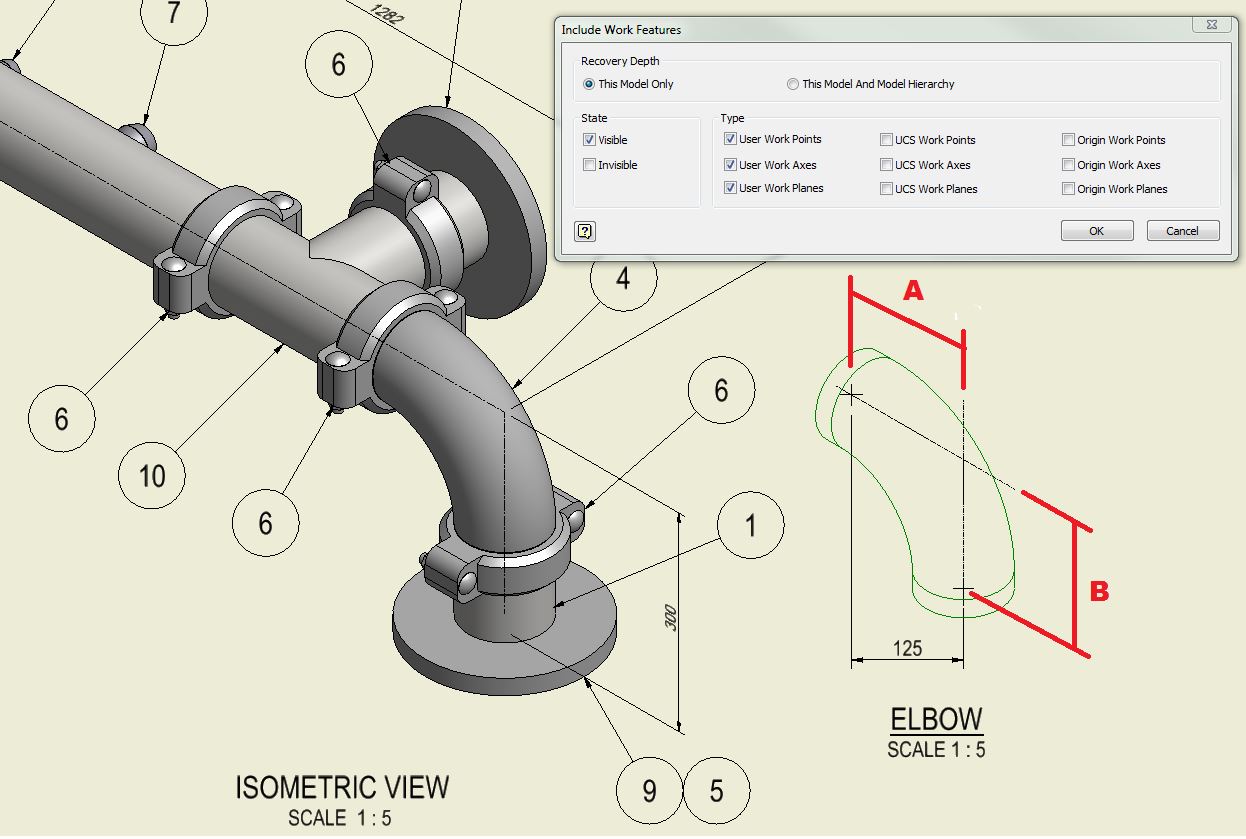
The image below shows a orthographic view of a butt welded pipe with three sizes (a, b, c). This single line is the centerline of the pipe, and from that line, the dimensions measured. Isometrics are not drawn to scale but should be proportional to easy understanding. The visualization, representation, and dimensioning of single, multiangle, and rolling offsets are explained..
Pipeline Isometric Drawings Explained NDT Techniques & Interpretation
The pipelines with all components and fittings are shown in a n isomertic drawing with a 30°/30° grid. The use of coordinate and elevation callouts to determine configuration dimensions of the routed pipe is explained. These highly structured drawings provide a comprehensive 3d representation of the arrangement, dimensions, and connections of pipes within a system. Web tube & pipe: How.
How to Draw Isometric Pipe Drawings in Autocad Gautier Camonect
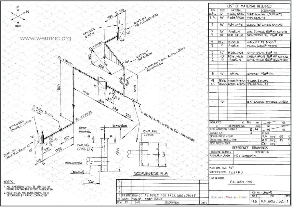
It shows all information necessary for fabrication and erection. Web piping technical trainer. Web drawing piping isometrics : Web an isometric drawing is a type of pictorial drawing in which three sides of an object can be seen in one view. Web piping isometric drawing consists of three sections.
Piping Isometric Drawing at Explore collection of
Web the fitting, flange, and valve drawing symbols unique to isometrics are depicted. Quickly produce installation isometrics and fabrication spool drawings. Work from hand sketches or just draw them directly. Isometric drawings are typically used to show the details of a piping system, such as the size and type of piping, the direction of flow of the fluids, and the.
Learn isometric drawings (piping isometric)
Main graphic section consist of isometric representation of a pipe line route in 3d space, which includes following information : As you draw, the bom generates and updates itself automatically. Web what are pipeline isometric drawings? It shows all information necessary for fabrication and erection. Web drawing an isometric proportionally simply means drawing a 10m run of pipe twice as.
Piping Isometric Drawings Autodesk Community
This single line is the centerline of the pipe, and from that line, the dimensions measured. In the world of industrial projects, precision and accuracy are of utmost importance. Generating isometrics | autodesk virtual academy. 254k views 2 years ago. Web a piping isometric drawing is a simplified representation of a pipeline system.
Web Piping Technical Trainer.
This is done by drawing the lines parallel to isometric axes. Symbols are shown in black lines. Web drawing an isometric proportionally simply means drawing a 10m run of pipe twice as long as a 5m length of pipe. Isometrics are not drawn to scale but should be proportional to easy understanding.
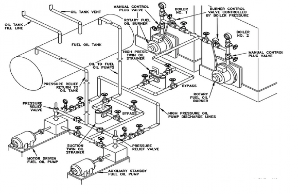
1) Show All Major Equipment, Its North/South And East/West Orientation, And All Piping Leading To And From Equipment Are Developed By Piping Designers.
Construction techniques for isometric drawing. Web a piping isometric drawing provides all the required information like: Piping plan drawings/general arrangement drawings (gad) the piping plan or general arrangement drawings (fig. Dimension is given relative to.
Piping Isometric Drawings Are Detailed Technical Illustrations That Show A 3D View Of Piping Systems.
How to read isometric drawing in a piping isometrics drawing, pipe is drawn according to it’s length,. How to read iso drawings. It’s popular within the process piping industry because it can be laid out and drawn with ease and portrays the. Generating isometrics | autodesk virtual academy.
This Single Line Is The Centerline Of The Pipe, And From That Line, The Dimensions Measured.
Web piping isometric drawing consists of three sections. It contains the dimensions of the pipeline route and the position of the piping components in isometric projection. They serve as precise illustrations providing essential information about the layout, dimensions, materials, and key components of a pipeline system. Are drawings which shows details of process pipe lines in a single line presentation , with details of pipes, pipe connections ( valves, flanges, nipples, reducers, end cap, elbow, etc), along with the dimensions and direction of pipe line.