Isometric Drawing Of Pipe
Isometric Drawing Of Pipe - Piping joint types, weld types. Web an extensive discussion of the need for, and development of, piping isometric drawings is provided. Web isometric drawings are typically used to show the details of a piping system, such as the size and type of piping, the direction of flow of the fluids, and the location of valves, pumps, and other equipment nozzles. Web basic piping isometric symbols : Web a piping isometric drawing provides all the required information like: What is covered in this course. No more tedious material tracking when creating a pipe isometric drawing. So, not from the outside of a pipe or fitting. The drawing axes of the isometrics intersect at an angle of 60°. Web a piping isometric drawing is a technical drawing that depicts a pipe spool or a complete pipeline using an isometric representation.
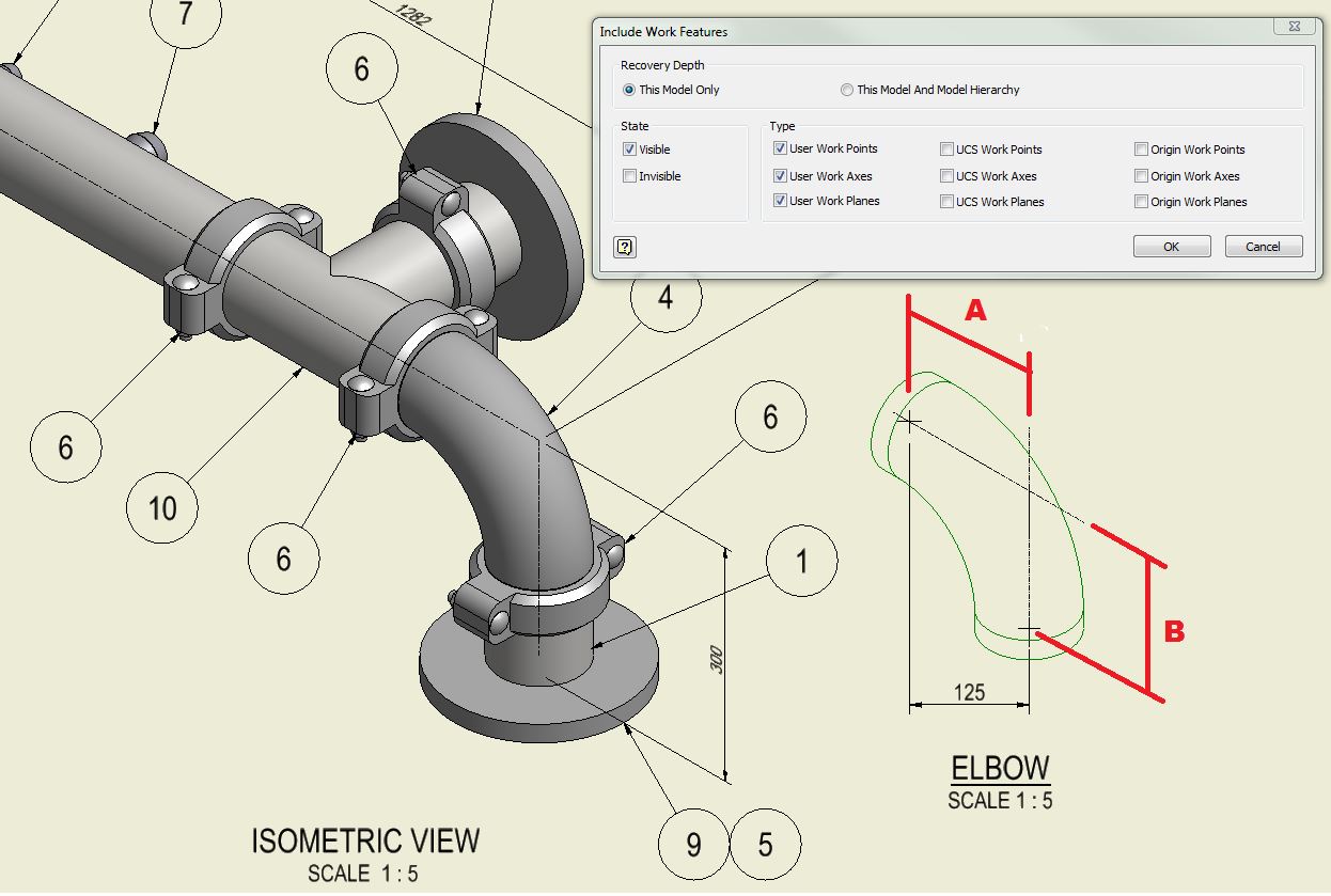
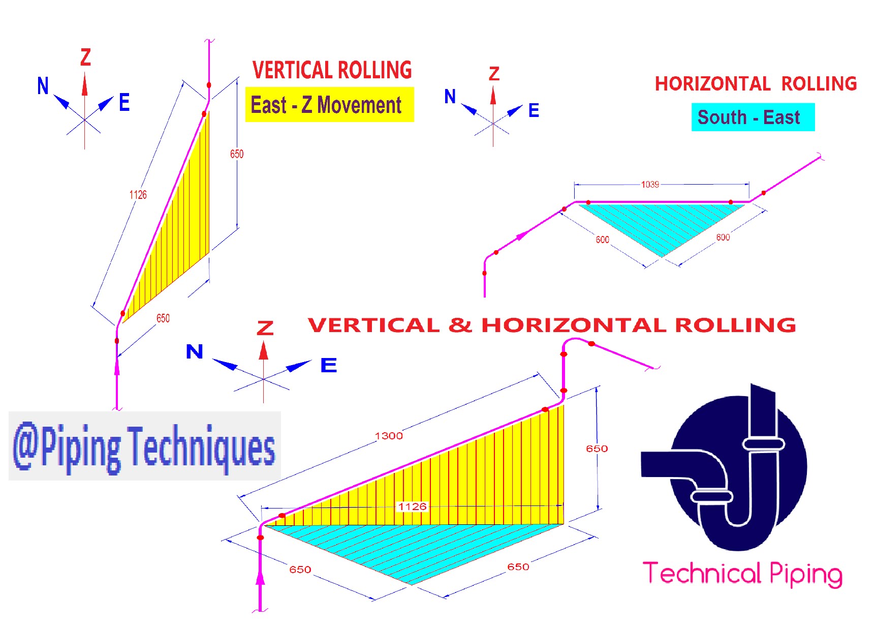
This single line is the centerline of the pipe, and from that line, the dimensions measured. Dimensions and location of instruments. How to read iso drawings. Web basic piping isometric symbols : The image below shows a orthographic view of a butt welded pipe with three sizes (a, b, c). Unlike orthographic drawings that show different views (front, side, and top) separately, isometric drawings combine these views into a. Subscribe to autodesk virtual academy. Piping isometric drawing consists of three sections. Web learn how to draw the correct information from piping isometrics like a pro (pipe, fittings, flanges, valves, offsets, schedules, pound ratings.) The use of a north arrow in establishing pipe orientation and routing on the isometric is shown graphically.
Piping isometric drawing consists of three sections. The direction should be selected so as to facilitate easy checking of isometrics with ga. Isometric drawings are commonly used in industries such as the oil and gas industry, petrochemical industry, and plumbing for planning, design, construction, and pipeline maintenance. How to read iso drawings. Pipe size is always written at any connecting point of isometric. They serve as precise illustrations providing essential information about the layout, dimensions, materials, and key components of a pipeline system. Web how to read piping isometric drawing symbols. Web piping isometric drawing is an isometric representation of single pipe line in a plant. Web pipeline isometrics are detailed drawings used in engineering and design to represent the 3d layout of a pipeline system on a 2d surface. Web a piping isometric drawing provides all the required information like:

Piping Isometric Drawing at Explore collection of
It is an axonometric projection in which the three coordinate axes appear equally foreshortened and the angle between any two of them is 120 degrees. Isolating, venting & draining symbols for ease of maintenance; Web how to read piping isometrics using real plant drawings. Web learn how to draw the correct information from piping isometrics like a pro (pipe, fittings,.

How to read piping Isometric drawing YouTube
Piping fabrication work is based on isometric drawings. Dimensions and location of instruments. It is the most important deliverable of piping engineering department. Pipe size is always written at any connecting point of isometric. Piping isometric drawing is a representation of 3d view of piping layout of the plant.

How to Draw Isometric Pipe Drawings in Autocad Gautier Camonect
This single line is the centerline of the pipe, and from that line, the dimensions measured. Web isometric drawings are typically used to show the details of a piping system, such as the size and type of piping, the direction of flow of the fluids, and the location of valves, pumps, and other equipment nozzles. 7.7k views 1 year ago.

How to read piping isometric drawing, Pipe fitter training, Watch the
No more tedious material tracking when creating a pipe isometric drawing. It’s popular within the process piping industry because it can be laid out and drawn with ease and portrays the. It is the most important deliverable of piping engineering department. Web a piping isometric drawing is a technical drawing that depicts a pipe spool or a complete pipeline using.

How to read isometric drawing piping dadver
What is covered in this course. Web piping isometric drawing is an isometric representation of single pipe line in a plant. Isometric drawings are commonly used in industries such as the oil and gas industry, petrochemical industry, and plumbing for planning, design, construction, and pipeline maintenance. Web to read piping isometric drawing you must know the following things: It’s popular.
Piping Isometric Drawings Autodesk Community
What you will get in this course. Web piping isometric drawing is an isometric representation of single pipe line in a plant. Web to read piping isometric drawing you must know the following things: Web the minimum inputs for isometric sketching are: Unlike orthographic drawings that show different views (front, side, and top) separately, isometric drawings combine these views into.
Automatic Piping Isometrics from 3D Piping Designs M4 ISO
Although the pipeline is accurately dimensioned, it is deliberately not drawn to scale and therefore does not correspond exactly to a real. Process & instrumentation diagram (p & id) 3. Web how to read piping isometric drawing symbols. Piping isometric drawing consists of three sections. What you will get in this course.
Piping Isometric Drawing at Explore collection of
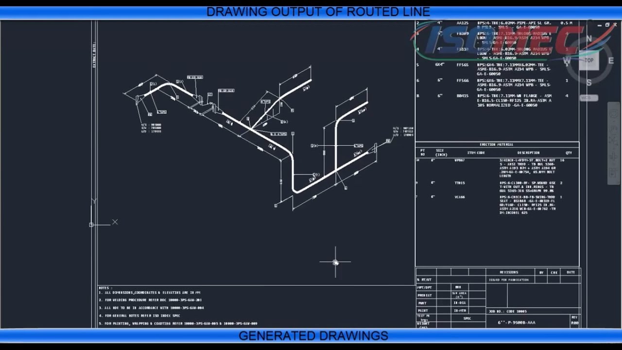
Web how to read piping isometrics using real plant drawings. An explanation of how piping isometrics are created from plan and elevation views is explained. Piping isometric drawing dimensions are always from center to center of pipe. Web a piping isometric drawing is a technical illustration that presents a 3d representation of a piping system. Although the pipeline is accurately.
Isometric Pipe Drawing at GetDrawings Free download
Web what are pipeline isometric drawings? In the world of industrial projects, precision and accuracy are of utmost importance. Mechanical data sheets (mds) in some of the cases, more detailed piping layout will be available. Web a piping isometric drawing provides all the required information like: It is an axonometric projection in which the three coordinate axes appear equally foreshortened.
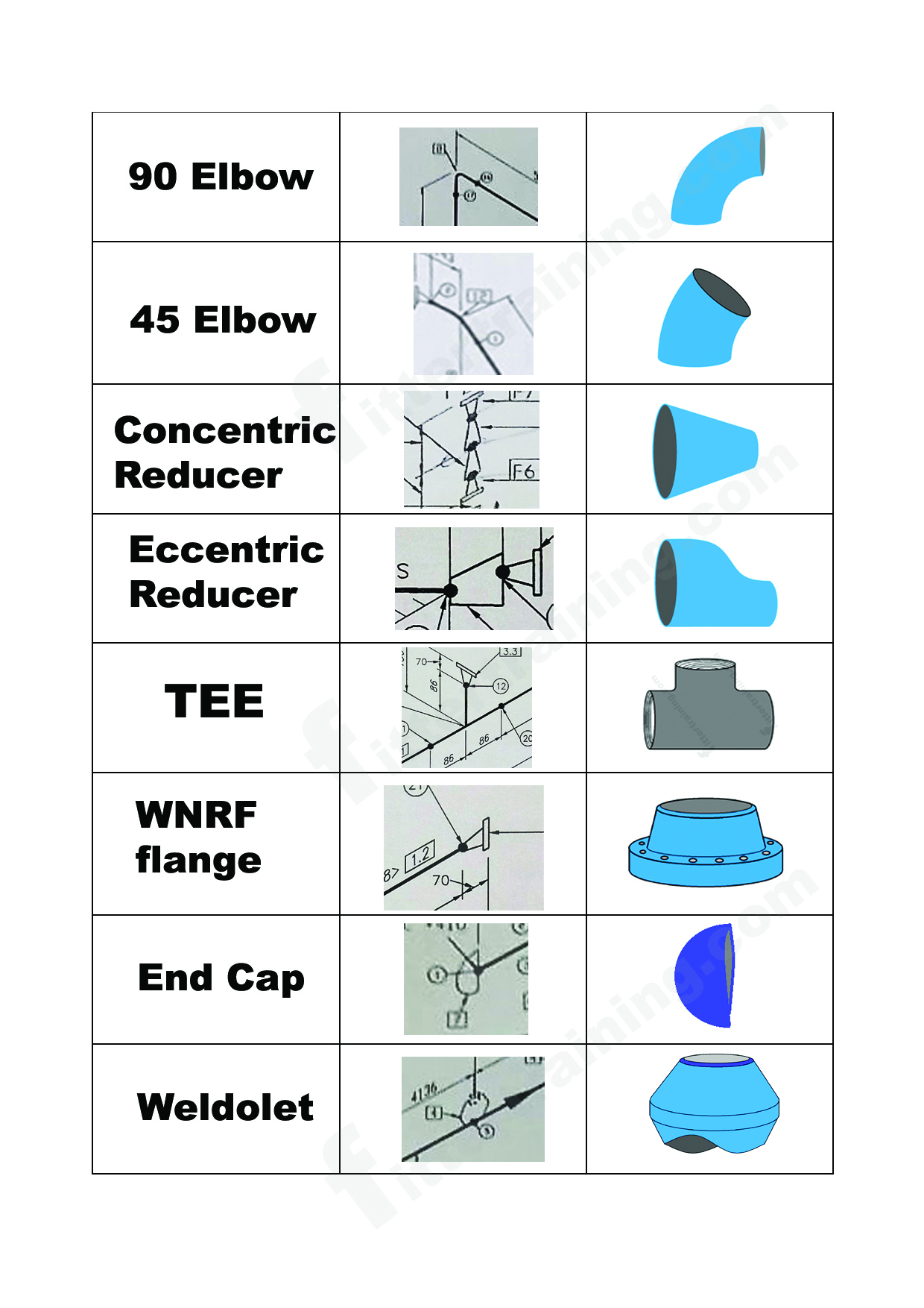
isometric pipe drawing fittings symbol Fitter training
Piping fabrication work is based on isometric drawings. 9k views 2 years ago autodesk inventor | ketiv virtual academy. Piping isometric drawing consists of three sections. So, not from the outside of a pipe or fitting. What is covered in this course.
Piping Isometric Drawing Consists Of Three Sections.
Isolating, venting & draining symbols for ease of maintenance; Web a piping isometric drawing provides all the required information like: It is an axonometric projection in which the three coordinate axes appear equally foreshortened and the angle between any two of them is 120 degrees. 3.5+ hours of high quality video lessons.
The Drawing Axes Of The Isometrics Intersect At An Angle Of 60°.
Piping fabrication work is based on isometric drawings. Although the pipeline is accurately dimensioned, it is deliberately not drawn to scale and therefore does not correspond exactly to a real. These highly structured drawings provide a comprehensive 3d representation of the arrangement, dimensions, and connections of pipes within a system. Web a pipe into a isometric view, is always drawn by a single line.
How To Read Iso Drawings.
Web easy isometric is the first pipe isometric drawing app that helps users make detailed isometric drawings in the field and without the need for tedious reference materials. Web learn how to draw the correct information from piping isometrics like a pro (pipe, fittings, flanges, valves, offsets, schedules, pound ratings.) This single line is the centerline of the pipe, and from that line, the dimensions measured. The image below shows a orthographic view of a butt welded pipe with three sizes (a, b, c).
Web An Extensive Discussion Of The Need For, And Development Of, Piping Isometric Drawings Is Provided.
9k views 2 years ago autodesk inventor | ketiv virtual academy. Reference number of pefs (p&id), ga drawings, line numbers, the direction of flow, and insulation tracing. Piping isometric drawings are detailed technical illustrations that show a 3d view of piping systems. Subscribe to autodesk virtual academy.