Isometric Drawing Symbols For Piping
Isometric Drawing Symbols For Piping - The direction should be selected so as to facilitate easy checking of isometrics with ga. Isolating, venting & draining symbols for ease of maintenance; Discover the essentials of piping isometrics, including how they simplify complex piping systems for construction, maintenance, and documentation purposes. An isometric drawing is a type of pictorial drawing in which three sides of an object can be seen in one view. Piping isometric dwg symbols designed just for you in autocad. Piping isometric drawing consists of three sections. Some individuals will not see these in their line of work but it is important to be aware of them. Lighter lines show connected pipe, and are not parts of the symbols. These tools generate the 3d representation of the piping layout, including pipe dimensions, fittings, valves,. Comprehensive depiction of fittings, connections, and supports, aiding in the construction and maintenance of the system.
Web basic piping isometric symbols : 7 provides symbols for pipe and pipe fittings. 8 provides symbols for noise. It is the most important deliverable of piping engineering department. Reference number of pefs (p&id), ga drawings, line numbers, the direction of flow, and insulation tracing. Web various symbols are used to indicate piping components, instrumentation, equipments in engineering drawings such as piping and instrumentation diagram (p&id), isometric drawings, plot plan, equipment layout, welding drawings etc. Web piping isometric drawing is an isometric representation of single pipe line in a plant. The direction should be selected so as to facilitate easy checking of isometrics with ga. Web master piping isometrics with our comprehensive guide: Web isometric symbols for piping fittings.
Pipe drafting and design roy a. Precise representation of piping components and their relationships, ensuring compatibility and functionality. Unlike orthographics, piping isometrics allow the pipe to be drawn in a manner by which the length, width and depth are shown in a single view. Web the fitting, flange, and valve drawing symbols unique to isometrics are depicted. Understanding these symbols is crucial for accurately interpreting the drawing and ensuring seamless integration of fittings within the overall piping system. Lighter lines show connected pipe, and are not parts of the symbols. In this dwg file you will find a huge collection of pipeline isometric drawings which are created in 2d format. Pipe drawings are much different from specific weld symbols but they do have a similar relationship from part to symbol. How to draw isometric piping drawings. The drawing axes of the isometrics intersect at an angle of 60°.

What is Piping Isometric drawing? How to Read Piping Drawing? ALL
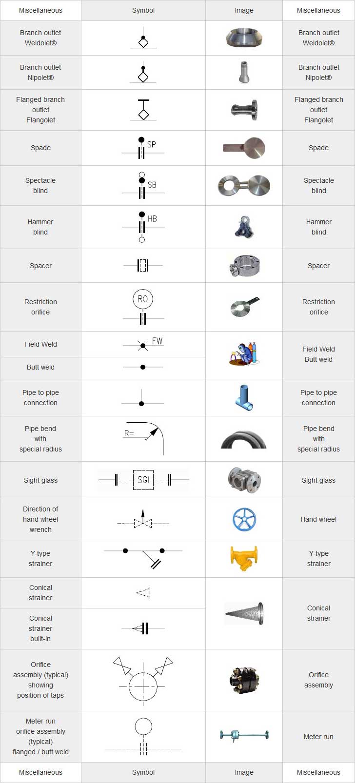
5 provides symbols for fans, pumps, and turbines. Web the fitting, flange, and valve drawing symbols unique to isometrics are depicted. Standards and conventions for valve status; Pressure, temperature, flow, level, switches, alarms, and miscellaneous. Checkout list of such symbols given below.

How to read piping isometric drawing pdf fleetlio
Piping fabrication work is based on isometric drawings. Which will help you with the fabrication and erection of the pipe in its proper location. Web a piping isometric drawing is a technical drawing that depicts a pipe spool or a complete pipeline using an isometric representation. Web piping isometric drawing software is an essential tool for piping engineers and designers.
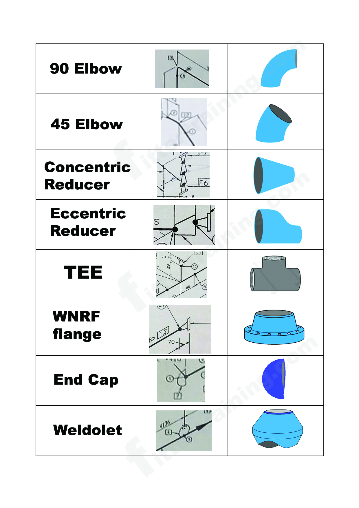
isometric pipe drawing fittings symbol Fitter training
7 provides symbols for pipe and pipe fittings. Pressure, temperature, flow, level, switches, alarms, and miscellaneous. Reference number of pefs (p&id), ga drawings, line numbers, the direction of flow, and insulation tracing. Web piping isometric drawing software is an essential tool for piping engineers and designers to create detailed isometric drawings of piping systems. Web these symbols are categorized under.

Piping Isometric Drawing Symbols Pdf at Explore
Unlike orthographics, piping isometrics allow the pipe to be drawn in a manner by which the length, width and depth are shown in a single view. Pressure, temperature, flow, level, switches, alarms, and miscellaneous. Web basic piping isometric symbols : These tools generate the 3d representation of the piping layout, including pipe dimensions, fittings, valves,. How to calculate reinforcement pad.
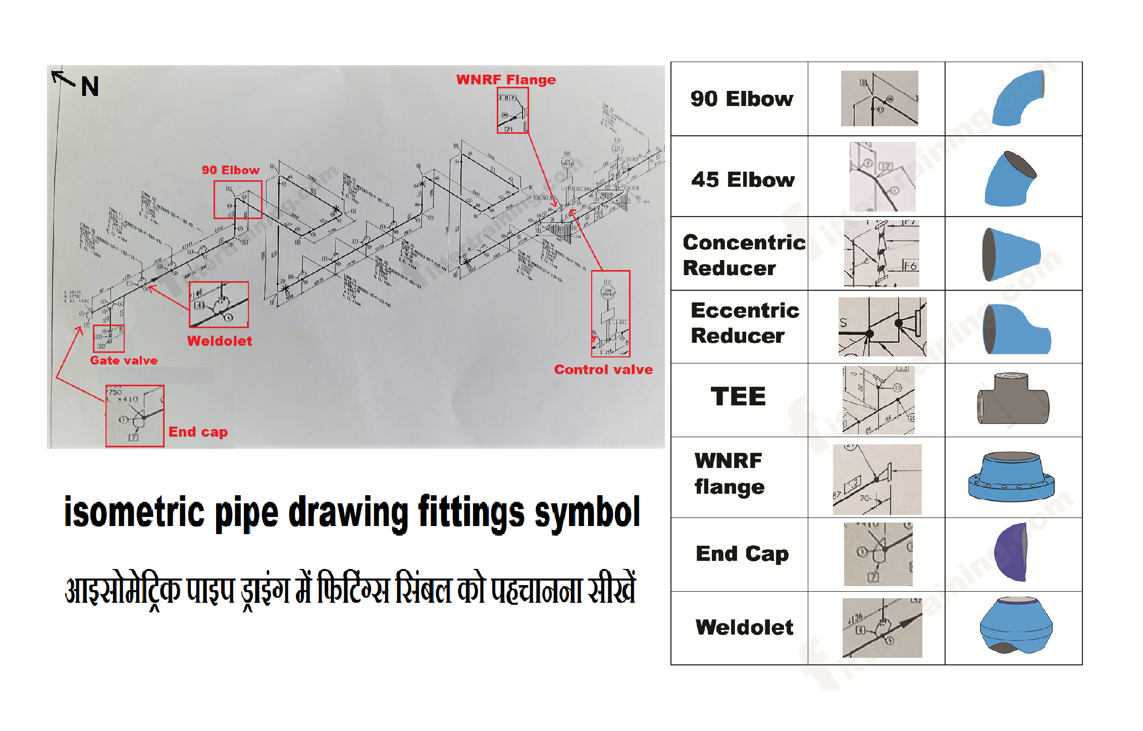
isometric pipe drawing fittings symbol Fitter training
Which will help you with the fabrication and erection of the pipe in its proper location. Piping isometric dwg symbols designed just for you in autocad. Visit our website and download all the drawings you like. How to draw isometric piping drawings. Web a piping isometric drawing is a technical drawing that depicts a pipe spool or a complete pipeline.
Piping Coordination System Mechanical symbols for Isometric drawings
Lighter lines show connected pipe, and are not parts of the symbols. Checkout list of such symbols given below. These tools generate the 3d representation of the piping layout, including pipe dimensions, fittings, valves,. An isometric drawing is a type of pictorial drawing in which three sides of an object can be seen in one view. The direction should be.

Isometric drawing for piping lmsop
Some individuals will not see these in their line of work but it is important to be aware of them. The visualization, representation, and dimensioning of single, multiangle, and rolling offsets are explained. Web isometric drawing piping symbols , terence m. Pipe drawings are much different from specific weld symbols but they do have a similar relationship from part to.
Piping Coordination System Mechanical symbols for Isometric drawings
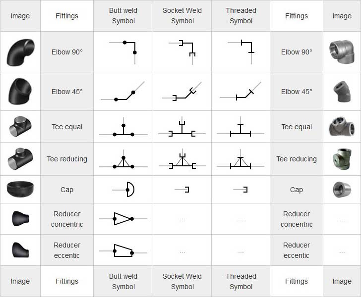
Piping isometric dwg symbols designed just for you in autocad. Pipe drafting and design roy a. Understanding these symbols is crucial for accurately interpreting the drawing and ensuring seamless integration of fittings within the overall piping system. In accordance with iso standards, each fitting has a unique symbol. How to draw isometric piping drawings.

Piping Isometric Drawings The Piping Engineering World
Web the fitting, flange, and valve drawing symbols unique to isometrics are depicted. Web what is an isometric drawing? Lighter lines show connected pipe, and are not parts of the symbols. Symbols for piping and instrumentation diagrams (pid). In accordance with iso standards, each fitting has a unique symbol.

Basic Piping Isometric Symbols Piping Analysis YouTube
Web how to read piping isometric drawing symbols. Isolating, venting & draining symbols for ease of maintenance; Symbols are shown in black lines. An isometric drawing is a type of pictorial drawing in which three sides of an object can be seen in one view. These tools generate the 3d representation of the piping layout, including pipe dimensions, fittings, valves,.
How To Calculate Reinforcement Pad Dimensions?
In this dwg file you will find a huge collection of pipeline isometric drawings which are created in 2d format. An isometric drawing is a type of pictorial drawing in which three sides of an object can be seen in one view. It is the most important deliverable of piping engineering department. Standards and conventions for valve status;
The Visualization, Representation, And Dimensioning Of Single, Multiangle, And Rolling Offsets Are Explained.
Reading tips, symbols, and drawing techniques for engineers and piping professionals. Web piping isometric drawing software is an essential tool for piping engineers and designers to create detailed isometric drawings of piping systems. Symbols for piping and instrumentation diagrams (pid). 8 provides symbols for noise.
Pressure, Temperature, Flow, Level, Switches, Alarms, And Miscellaneous.
Web these include elbows, tees, reducers, and couplings. 6 provides symbols for plumbing components. Precise representation of piping components and their relationships, ensuring compatibility and functionality. Web the fitting, flange, and valve drawing symbols unique to isometrics are depicted.
Reference Number Of Pefs (P&Id), Ga Drawings, Line Numbers, The Direction Of Flow, And Insulation Tracing.
Understanding these symbols is crucial for accurately interpreting the drawing and ensuring seamless integration of fittings within the overall piping system. Symbols are shown in black lines. Piping isometric dwg symbols designed just for you in autocad. Pipe drafting and design roy a.