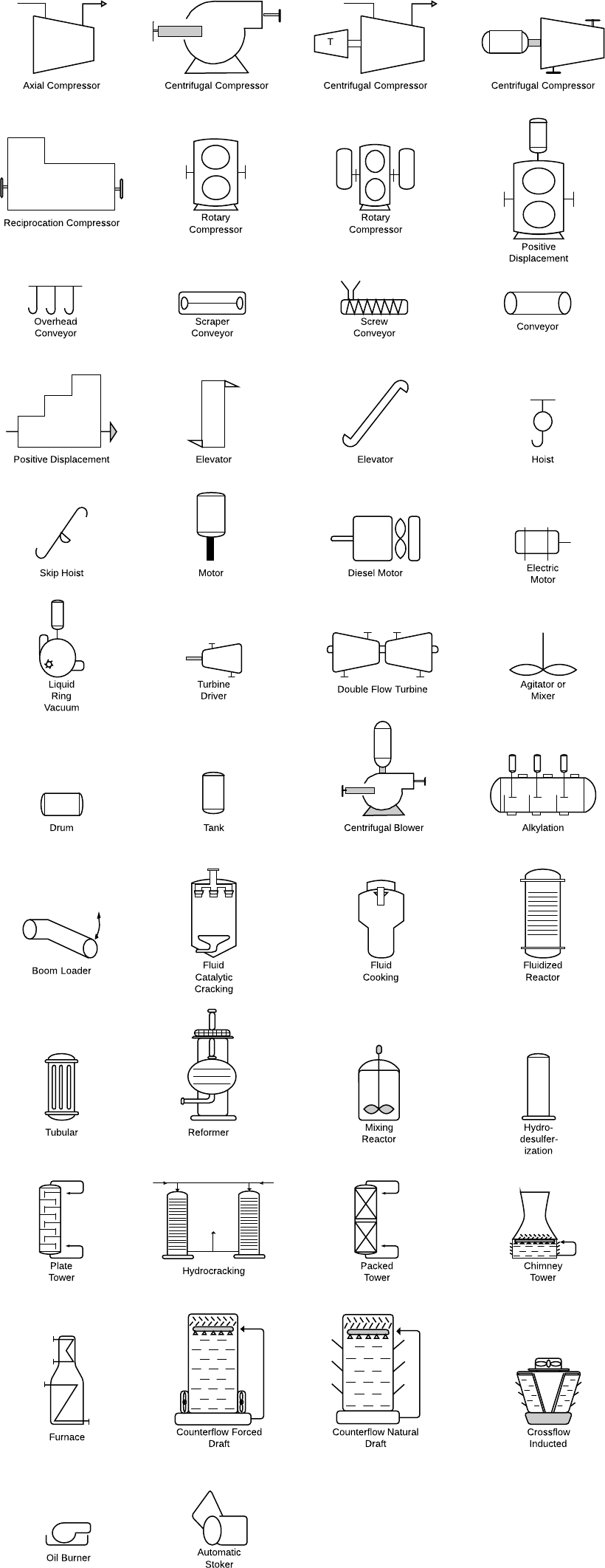
Isometric Pipe Drawing Symbols
Isometric Pipe Drawing Symbols - Web basic piping isometric symbols : Web piping isometric drawing software is an essential tool for piping engineers and designers to create detailed isometric drawings of piping systems. Web how to read piping isometric drawing symbols. Piping iso symbols and meaning. Web various symbols are used to indicate piping components, instrumentation, equipments in engineering drawings such as piping and instrumentation diagram (p&id), isometric drawings, plot plan, equipment layout, welding drawings etc. Web isometric drawing symbols for piping valves. With help of the coordinate system in piping isometric drawing, length of pipe can be calculated by subtracting two northing, two eastings, or two elevation values. Standards and conventions for valve status; Web isometric drawing piping symbols , terence m. Browse productsmultiple payment methodschat support availableno sales tax
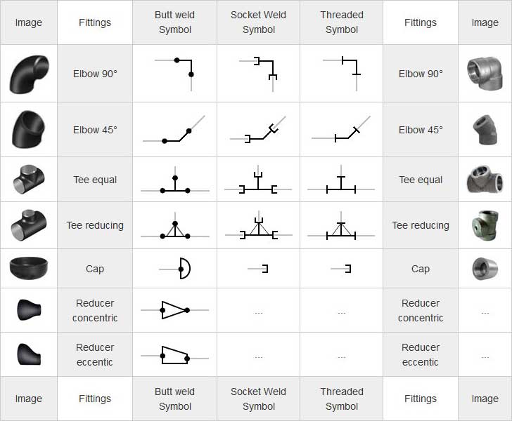
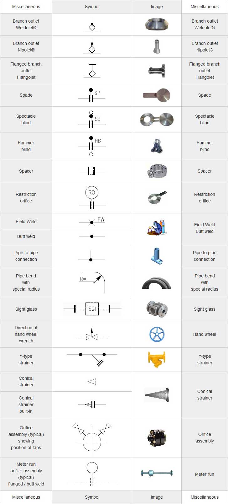
In addition, an piping isometric drawing can contain further information about the components it contains by means of text annotation. Web how to read piping isometric drawing symbols. Inlet/outlet bolt scope of supply. Web of the symbol will be left to the discretion of the activity concerned, provided that the symbol used does not duplicate any of those contained herein, and is clearly understandable, Each symbol carries a specific meaning, akin to words in a language. Browse productsmultiple payment methodschat support availableno sales tax These drawings essentially provide a detailed visual representation of complex piping systems. All of our vector cad models are of the highest quality. Importance of piping isometrics to the construction, commissioning, safe operation and maintenance of a process plant. As with weld symbols, pipe symbols are a reflection of what that part would look like in.
Understanding these symbols is crucial for anyone involved in the construction and maintenance of pipelines. Symbols are shown in black lines. Web isometric symbols for piping fittings. Web various symbols are used to indicate piping components, instrumentation, equipments in engineering drawings such as piping and instrumentation diagram (p&id), isometric drawings, plot plan, equipment layout, welding drawings etc. In addition, an piping isometric drawing can contain further information about the components it contains by means of text annotation. As you can see, this drawing is very simple and quick to implement. Web isometric drawing symbols for piping valves. Familiarity with these symbols is vital for planning inspections and pinpointing areas of concern. Standards and conventions for valve status; Project specific instructions for isometrics checking.
Piping Isometric Drawing Symbols Pdf at Explore
With help of the coordinate system in piping isometric drawing, length of pipe can be calculated by subtracting two northing, two eastings, or two elevation values. Web piping isometric drawing software is an essential tool for piping engineers and designers to create detailed isometric drawings of piping systems. Web ndt pipeline drawings often include specific symbols and annotations to indicate.

What is Piping Isometric drawing? How to Read Piping Drawing? ALL
Lighter lines show connected pipe, and are not parts of the symbols. Symbols are shown in black lines. Web isometric drawing symbols for piping valves. In addition, an piping isometric drawing can contain further information about the components it contains by means of text annotation. Web the isometric is commonly referred to as oriented towards the north direction marked with.
Piping Coordination System Mechanical symbols for Isometric drawings
From valves to pumps, each element has its unique representation in the isometric language. Web easy isometric is the first pipe isometric drawing app that helps users make detailed isometric drawings in the field and without the need for tedious reference materials. In this dwg file you will find a huge collection of pipeline isometric drawings which are created in.

How to read isometric drawing piping dadver
Browse productsmultiple payment methodschat support availableno sales tax With help of the coordinate system in piping isometric drawing, length of pipe can be calculated by subtracting two northing, two eastings, or two elevation values. Isolating, venting & draining symbols for ease of maintenance; As with weld symbols, pipe symbols are a reflection of what that part would look like in..
Piping Coordination System Mechanical symbols for Isometric drawings
Web (double line presentation) isometric view. Every project has specific requirements. The red lines show the pipe, the black dots are the butt welds and a, b and c are the dimensions of front to center line and center line to center line. Familiarity with these symbols is vital for planning inspections and pinpointing areas of concern. From valves to.

Piping Isometric Drawing Symbols Pdf at Explore
Web various symbols are used to indicate piping components, instrumentation, equipments in engineering drawings such as piping and instrumentation diagram (p&id), isometric drawings, plot plan, equipment layout, welding drawings etc. Some individuals will not see these in their line of work but it is important to be aware of them. The isometric view shows the same pipe as in the.
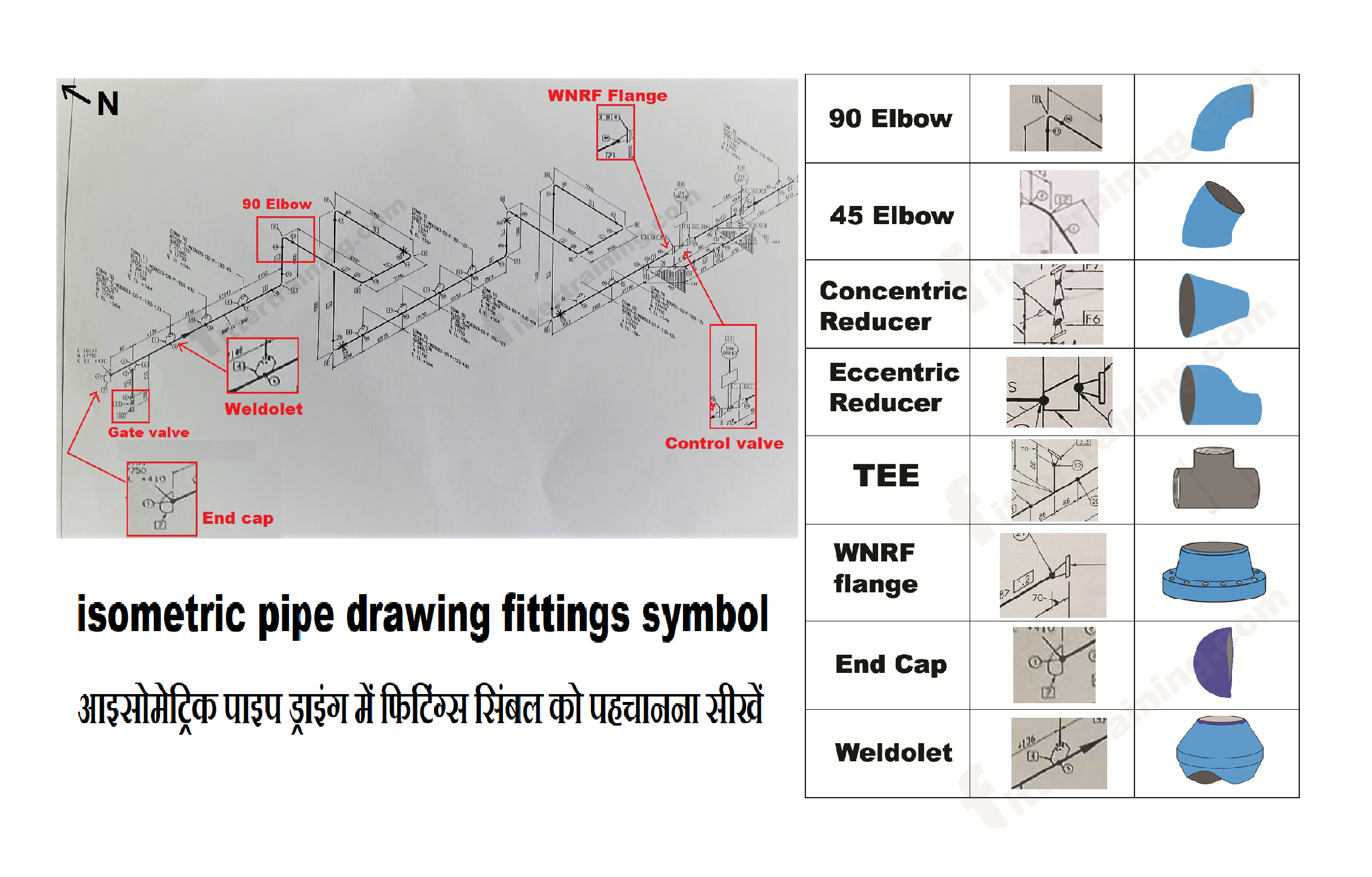
isometric pipe drawing fittings symbol Fitter training
The isometric view shows the same pipe as in the orthographic view. These needs to be reflected in isometrics drawings. In addition, an piping isometric drawing can contain further information about the components it contains by means of text annotation. Web how to read piping isometric drawing symbols. Every project has specific requirements.

Piping Isometric Drawings The Piping Engineering World
Web of the symbol will be left to the discretion of the activity concerned, provided that the symbol used does not duplicate any of those contained herein, and is clearly understandable, It’s crucial to read and understand these drawings for professionals in various industries like oil and gas and manufacturing. As with weld symbols, pipe symbols are a reflection of.
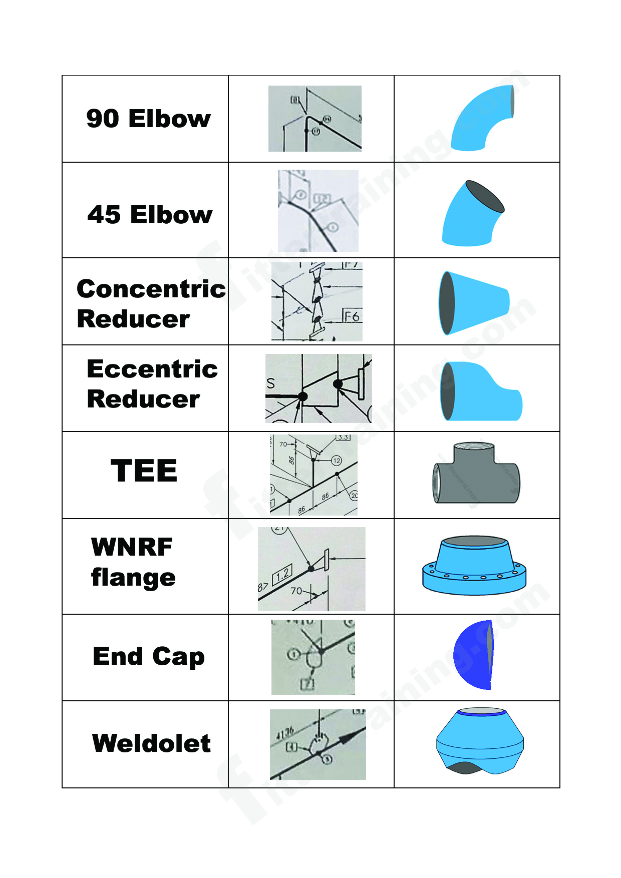
isometric pipe drawing fittings symbol Fitter training
Every project has specific requirements. Some of these requirements can be regarding following points. Each symbol carries a specific meaning, akin to words in a language. Browse productsmultiple payment methodschat support availableno sales tax These needs to be reflected in isometrics drawings.

Basic Piping Isometric Symbols Piping Analysis YouTube
These drawings are impelled to supply a more detailed and authentic representation, emphasising the pipes, valves and other components’ shape, size and. Web how to read piping isometric drawing symbols. It’s crucial to read and understand these drawings for professionals in various industries like oil and gas and manufacturing. As you can see, this drawing is very simple and quick.
Piping Isometric Dwg Symbols Designed Just For You In Autocad.
Web (double line presentation) isometric view. Symbols are shown in black lines. These needs to be reflected in isometrics drawings. In addition, an piping isometric drawing can contain further information about the components it contains by means of text annotation.
Web Isometric Drawing Piping Symbols , Terence M.
Some of these requirements can be regarding following points. Web the isometric is commonly referred to as oriented towards the north direction marked with an arrow in the top right corner. All of our vector cad models are of the highest quality. Web isometric drawing symbols for piping valves.
Every Project Has Specific Requirements.
How to read piping isometrics using real plant drawings. Visit our website and download all the drawings you like. Web of the symbol will be left to the discretion of the activity concerned, provided that the symbol used does not duplicate any of those contained herein, and is clearly understandable, These drawings are impelled to supply a more detailed and authentic representation, emphasising the pipes, valves and other components’ shape, size and.
Inlet/Outlet Bolt Scope Of Supply.
As you can see, this drawing is very simple and quick to implement. Project specific instructions for isometrics checking. The red lines show the pipe, the black dots are the butt welds and a, b and c are the dimensions of front to center line and center line to center line. With help of the coordinate system in piping isometric drawing, length of pipe can be calculated by subtracting two northing, two eastings, or two elevation values.