Mech Drawing Symbols
Mech Drawing Symbols - Web category chemical engineering. True position theory (size value in rectangular frame) classification and symbols of geometric tolerance characteristics. This list includes abbreviations common to the vocabulary of people who work with engineering drawings in the manufacture and inspection of parts and assemblies. Symbols shown below are generally based on bs 7845:1996 , bs 3939 and bs en 60617. Engineering drawing symbols play a vital role in communication among engineers and other stakeholders involved in the design and construction process. Learn the symbols, the important information, how to read it and where we use them. Work with runsom for your cnc programming projects. Common symbols used in mechanical schematic diagrams include arrows, rectangles, circles, diamonds, and other shapes. Web basic types of symbols used in engineering drawings are countersink, counterbore, spotface, depth, radius, and diameter. More engineering drawing abbreviations can be used in cnc manufacturing;
Web category chemical engineering. Work with runsom for your cnc programming projects. This list includes abbreviations common to the vocabulary of people who work with engineering drawings in the manufacture and inspection of parts and assemblies. Learn the symbols, the important information, how to read it and where we use them. Need to know for dispelling uncertainty in drawings. Most symbols have been in y14.5 since at least 1994. Unlike a model, engineering drawings offer more specific detail and requirements,. Web what are the most commonly used engineering drawing symbols and their meanings? Note the comparison with the iso standards. There were no new gd&t symbols in the dimensioning section in.
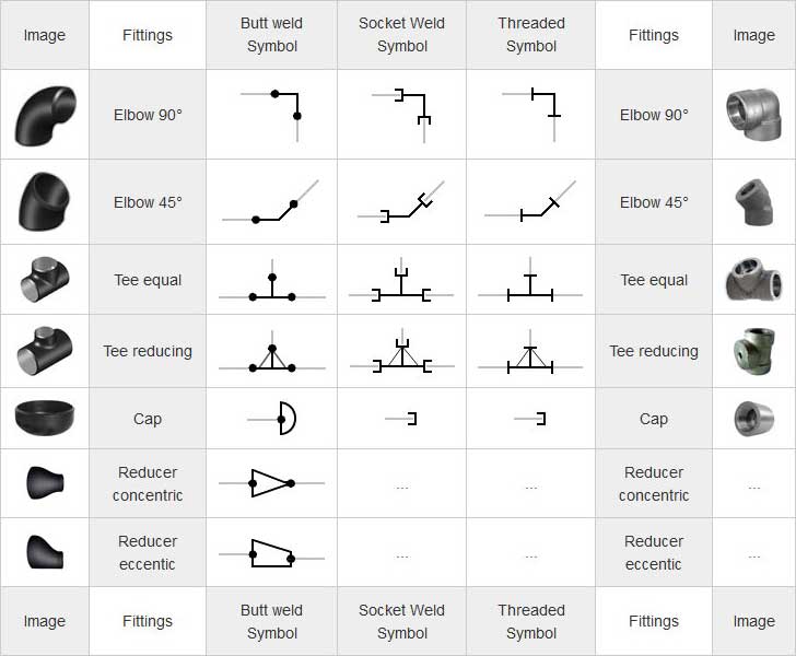
The table shows dimensioning symbols found on engineering and mechanical drawings. Conceptdraw diagram users have access to all of them and can insert them into the drawing by simply dragging and dropping: Web what are the most commonly used engineering drawing symbols and their meanings? There were no new gd&t symbols in the dimensioning section in. This makes it possible to quickly identify the various components in a given schematic. Common symbols used in mechanical schematic diagrams include arrows, rectangles, circles, diamonds, and other shapes. Web currently, we have 16 symbols for geometric tolerances, which are categorized according to the tolerance they specify. We offer you our tips which we believe are useful for dispelling uncertainty by comparing the symbol with its graphic representation. Symbols or conventions used on the drawing and any additional information the designeror draftsmanfeltwas necessaryto understandthedrawing. Note the comparison with the iso standards.

Mechanical Engineering Drawing Symbols Pdf Free Download at
There were no new gd&t symbols in the dimensioning section in. Classification and symbols of geometric tolerance characteristics. Dimensioning and tolerancing with 45 elements; Common symbols used in mechanical schematic diagrams include arrows, rectangles, circles, diamonds, and other shapes. Web graphical symbols for use on mechanical engineering and construction drawings, diagrams, plans, maps and in relevant technical product documentation

Mechanical Engineering Symbols Cadbull
Free courses learn how to read mechanical engineering schematic drawings. Conceptdraw diagram users have access to all of them and can insert them into the drawing by simply dragging and dropping: Work with runsom for your cnc programming projects. These symbols can include lines, boxes, circles, arcs and text. Web mechanical drawing symbols are used to represent components and processes.
Piping Coordination System Mechanical symbols for Isometric drawings
Unlike a model, engineering drawings offer more specific detail and requirements,. These symbols can include lines, boxes, circles, arcs and text. Click on the links below to learn more about each gd&t symbol or concept, and be sure to download the free wall chart for a quick reference when at your desk or on the shop floor. Web mechanical engineering.
Mechanical Engineering Drawing Symbols Pdf Free Download at
More engineering drawing abbreviations can be used in cnc manufacturing; We offer you our tips which we believe are useful for dispelling uncertainty by comparing the symbol with its graphic representation. Symbols shown below are generally based on bs 7845:1996 , bs 3939 and bs en 60617. There were no new gd&t symbols in the dimensioning section in. Dimensioning and.
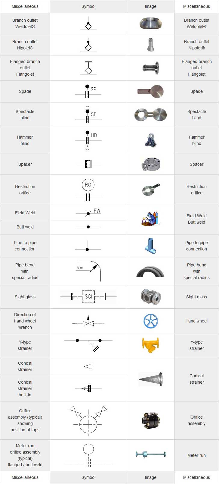
Piping Coordination System Mechanical symbols for Isometric drawings
Web the symbols used in mechanical schematic diagrams are usually standardized across all schematics. Web this section standardizes the symbols for specifying geometrical characteristics and other dimensional requirements on engineering drawings. This basic symbol consists of two legs of unequal length. Web basic types of symbols used in engineering drawings are countersink, counterbore, spotface, depth, radius, and diameter. Why abbreviations.

Mechanical Drawing Symbols Chart
Here are more commonly used engineering drawing symbols and design elements as below. How to read symbols in an engineering drawing? Conceptdraw diagram users have access to all of them and can insert them into the drawing by simply dragging and dropping: Web common drawing abbreviations and symbols of mechanical design and engineering; Web what are the most commonly used.

Mechanical Drawing Symbols
Web this section standardizes the symbols for specifying geometrical characteristics and other dimensional requirements on engineering drawings. Web what are the most commonly used engineering drawing symbols and their meanings? Lines are typically used for connecting different objects or parts of a diagram together, while boxes are used to show the size and shape of objects. Dimensioning and tolerancing with.
Mechanical Drawing Symbols
Click on the links below to learn more about each gd&t symbol or concept, and be sure to download the free wall chart for a quick reference when at your desk or on the shop floor. Need to know for dispelling uncertainty in drawings. Web mechanical drawing symbols are used to represent components and processes in diagrams. The table below.

M&e Drawing Symbols Back To Basics Komseq
Free courses learn how to read mechanical engineering schematic drawings. Note the comparison with the iso standards. An introduction to the different types of blueprint tolerances you will encounter with plenty of examples to make them easy to understand. The diagrams are produced using symbols as building block combining functional symbols with symbols for variability and operation and material. Symbols.

Mechanical Drawing Symbols Process Flow Diagram Symbols Electrical
Click on the links below to learn more about each gd&t symbol or concept, and be sure to download the free wall chart for a quick reference when at your desk or on the shop floor. You can also check out the gd&t symbols and terms on our site. These symbols can include lines, boxes, circles, arcs and text. Web.
Web What Are The Most Commonly Used Engineering Drawing Symbols And Their Meanings?
Here are more commonly used engineering drawing symbols and design elements as below. Web currently, we have 16 symbols for geometric tolerances, which are categorized according to the tolerance they specify. Web category chemical engineering. Web engineering drawing abbreviations and symbols are used to communicate and detail the characteristics of an engineering drawing.
Common Symbols Used In Mechanical Schematic Diagrams Include Arrows, Rectangles, Circles, Diamonds, And Other Shapes.
You can also check out the gd&t symbols and terms on our site. More engineering drawing abbreviations can be used in cnc manufacturing; Click on the links below to learn more about each gd&t symbol or concept, and be sure to download the free wall chart for a quick reference when at your desk or on the shop floor. Web mechanical drawing symbols are used to represent components and processes in diagrams.
This List Includes Abbreviations Common To The Vocabulary Of People Who Work With Engineering Drawings In The Manufacture And Inspection Of Parts And Assemblies.
Most symbols have been in y14.5 since at least 1994. Web graphical symbols for use on mechanical engineering and construction drawings, diagrams, plans, maps and in relevant technical product documentation Web basic types of symbols used in engineering drawings are countersink, counterbore, spotface, depth, radius, and diameter. The table below shows symbols for the geometrical characteristics.
Unlike A Model, Engineering Drawings Offer More Specific Detail And Requirements,.
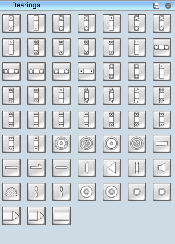
Web mechanical engineering solution offers 602 commonly used mechanical drawing symbols and objects which are professionally designed and grouped in 8 libraries. Web common drawing abbreviations and symbols of mechanical design and engineering; This makes it possible to quickly identify the various components in a given schematic. Lines are typically used for connecting different objects or parts of a diagram together, while boxes are used to show the size and shape of objects.