Mechanical Drawing Symbols
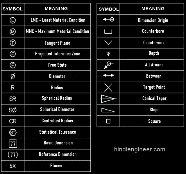
Mechanical Drawing Symbols - Web the table shows dimensioning symbols found on engineering and mechanical drawings. This list includes abbreviations common to the vocabulary of people who work with engineering drawings in the manufacture and inspection of parts and assemblies. Most symbols have been in y14.5 since at least 1994. Any needed height h 2 h h 2 h 60° 2 h identification letter datum feature symbol datum target symbol target point and. An introduction to the different types of blueprint tolerances you will encounter with plenty of examples to make them easy to understand. It comes in useful if a feature is to be defined on a drawing that needs to be uniformly flat without tightening any other dimensions on. Unidirectional, the dimensions are written horizontally. Aligned, the dimensions are written parallel to their dimension line. Web a good design drawing can indicate all the details needed to produce a mechanical cnc milling part in an easy way. Web engineering drawing abbreviations and symbols are used to communicate and detail the characteristics of an engineering drawing.
Two methods of dimensioning are in common use. Gd&t flatness is a common symbol that references how flat a surface is regardless of any other datum’s or features. Web a good design drawing can indicate all the details needed to produce a mechanical cnc milling part in an easy way. Web engineering drawing abbreviations and symbols are used to communicate and detail the characteristics of an engineering drawing. It comes in useful if a feature is to be defined on a drawing that needs to be uniformly flat without tightening any other dimensions on. Web symbols or conventions used on the drawing and any additional information the designeror draftsmanfeltwas necessaryto understandthedrawing. An introduction to the different types of blueprint tolerances you will encounter with plenty of examples to make them easy to understand. Web standard symbols for mechanical components use such shapes as circles, ovals, arcs, triangles, squares, rectangles, polygons, lines, arrows, and other geometrical forms separately or arranged in complex patterns. Process piping sizes and identification. This list includes abbreviations common to the vocabulary of people who work with engineering drawings in the manufacture and inspection of parts and assemblies.
Ala hijazi engineering working drawings basics page 10 of 22. Web p&id engineering drawings differ from the typical mechanical variant; Web standard symbols for mechanical components use such shapes as circles, ovals, arcs, triangles, squares, rectangles, polygons, lines, arrows, and other geometrical forms separately or arranged in complex patterns. The following tables show how to construct the symbols. Web geometric dimensioning and tolerancing symbols you can either create your own library of gd&t symbols, or use one of autocad’s gd&t fonts to insert the symbols as text. Web engineering drawing abbreviations and symbols are used to communicate and detail the characteristics of an engineering drawing. Pipe classes and piping line. Web the table shows dimensioning symbols found on engineering and mechanical drawings. Gd&t flatness is a common symbol that references how flat a surface is regardless of any other datum’s or features. Most symbols have been in y14.5 since at least 1994.

Mechanical Engineering Drawing Symbols Pdf Free Download at
Because there is no large space on a drawing to contain all the text to illustrate the image, abbreviations, and symbols are often used in engineering drawings to communicate the characteristics of the product to be. The following tables show how to construct the symbols. It comes in useful if a feature is to be defined on a drawing that.
Radius Symbol Drafting
Pipe classes and piping line. Process piping sizes and identification. An introduction to the different types of blueprint tolerances you will encounter with plenty of examples to make them easy to understand. This list includes abbreviations common to the vocabulary of people who work with engineering drawings in the manufacture and inspection of parts and assemblies. Because there is no.

Mechanical Drawing Symbols Process Flow Diagram Symbols Electrical
Note the comparison with the iso standards. Web a good design drawing can indicate all the details needed to produce a mechanical cnc milling part in an easy way. Most symbols have been in y14.5 since at least 1994. It comes in useful if a feature is to be defined on a drawing that needs to be uniformly flat without.

Engineering Drawing Symbols And Their Meanings Pdf at PaintingValley
Web standard symbols for mechanical components use such shapes as circles, ovals, arcs, triangles, squares, rectangles, polygons, lines, arrows, and other geometrical forms separately or arranged in complex patterns. Web the table shows dimensioning symbols found on engineering and mechanical drawings. Web geometric dimensioning and tolerancing symbols you can either create your own library of gd&t symbols, or use one.

Mechanical Engineering Symbols Cadbull
Aligned, the dimensions are written parallel to their dimension line. Web a good design drawing can indicate all the details needed to produce a mechanical cnc milling part in an easy way. Any needed height h 2 h h 2 h 60° 2 h identification letter datum feature symbol datum target symbol target point and. Pipe classes and piping line..

Mechanical Engineering Drawing Symbols Pdf Free Download at
Any needed height h 2 h h 2 h 60° 2 h identification letter datum feature symbol datum target symbol target point and. Specific piping data can be read from a diagram, including: Gd&t flatness is a common symbol that references how flat a surface is regardless of any other datum’s or features. Web p&id engineering drawings differ from the.

Engineering Drawing Symbols And Their Meanings Pdf at PaintingValley
This list includes abbreviations common to the vocabulary of people who work with engineering drawings in the manufacture and inspection of parts and assemblies. Two methods of dimensioning are in common use. Web geometric dimensioning and tolerancing symbols you can either create your own library of gd&t symbols, or use one of autocad’s gd&t fonts to insert the symbols as.

Mechanical Drawing Symbols
Two methods of dimensioning are in common use. Web geometric dimensioning and tolerancing symbols you can either create your own library of gd&t symbols, or use one of autocad’s gd&t fonts to insert the symbols as text. Ala hijazi engineering working drawings basics page 10 of 22. Unidirectional, the dimensions are written horizontally. Any needed height h 2 h h.

M&e Drawing Symbols Back To Basics Komseq
Web standard symbols for mechanical components use such shapes as circles, ovals, arcs, triangles, squares, rectangles, polygons, lines, arrows, and other geometrical forms separately or arranged in complex patterns. This list includes abbreviations common to the vocabulary of people who work with engineering drawings in the manufacture and inspection of parts and assemblies. Ala hijazi engineering working drawings basics page.

Mechanical Engineering Drawing Symbols Pdf Free Download at
Web standard symbols for mechanical components use such shapes as circles, ovals, arcs, triangles, squares, rectangles, polygons, lines, arrows, and other geometrical forms separately or arranged in complex patterns. It comes in useful if a feature is to be defined on a drawing that needs to be uniformly flat without tightening any other dimensions on. Most symbols have been in.
Gd&T Flatness Is A Common Symbol That References How Flat A Surface Is Regardless Of Any Other Datum’s Or Features.
Pipe classes and piping line. Two methods of dimensioning are in common use. Any needed height h 2 h h 2 h 60° 2 h identification letter datum feature symbol datum target symbol target point and. Process piping sizes and identification.
It Comes In Useful If A Feature Is To Be Defined On A Drawing That Needs To Be Uniformly Flat Without Tightening Any Other Dimensions On.
Web a good design drawing can indicate all the details needed to produce a mechanical cnc milling part in an easy way. Note the comparison with the iso standards. Because there is no large space on a drawing to contain all the text to illustrate the image, abbreviations, and symbols are often used in engineering drawings to communicate the characteristics of the product to be. Web p&id engineering drawings differ from the typical mechanical variant;
Aligned, The Dimensions Are Written Parallel To Their Dimension Line.
Web the table shows dimensioning symbols found on engineering and mechanical drawings. Web symbols or conventions used on the drawing and any additional information the designeror draftsmanfeltwas necessaryto understandthedrawing. Web standard symbols for mechanical components use such shapes as circles, ovals, arcs, triangles, squares, rectangles, polygons, lines, arrows, and other geometrical forms separately or arranged in complex patterns. The following tables show how to construct the symbols.
Web Engineering Drawing Abbreviations And Symbols Are Used To Communicate And Detail The Characteristics Of An Engineering Drawing.
An introduction to the different types of blueprint tolerances you will encounter with plenty of examples to make them easy to understand. Specific piping data can be read from a diagram, including: Unidirectional, the dimensions are written horizontally. Ala hijazi engineering working drawings basics page 10 of 22.