Mechanical Technical Drawing Symbols
Mechanical Technical Drawing Symbols - Web mechanical engineering solution offers 602 commonly used mechanical drawing symbols and objects which are professionally designed and grouped in 8 libraries. Web mechanical engineering solution — 8 libraries are available with 602 commonly used mechanical drawing symbols in mechanical engineering solution, including libraries called bearings with 59 elements of roller and ball bearings, shafts, gears, hooks, springs, spindles and keys; Note the comparison with the iso standards. Web mechanical engineering solution — 8 libraries are available with 602 commonly used mechanical drawing symbols in mechanical engineering solution, including libraries called bearings with 59 elements of roller and ball bearings, shafts, gears, hooks, springs, spindles and keys; Dimensioning and tolerancing with 45 elements; Symbols or conventions used on the drawing and any additional information the designeror draftsmanfeltwas necessaryto understandthedrawing. Drawing views are simply the representation of your. The following tables show how to construct the symbols. Web a good design drawing can indicate all the details needed to produce a mechanical cnc milling part in an easy way. Web an engineering (or technical) drawing is a graphical representation of a part, assembly, system, or structure and it can be produced using freehand, mechanical tools, or computer methods.
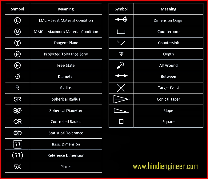
Toleranced characteristics and symbols — examples of indication and interpretation. For example, r6 means the circle has a radius of 6mm. In learning drafting, we will approach it from the perspective of manual drafting. Web the table shows dimensioning symbols found on engineering and mechanical drawings. Arcs are also dimensioned on drawing with a radius. Dimensioning and tolerancing with 45 elements; Dimensioning and tolerancing with 45 elements; There are 7 aspects of the gd&t methodology that we will discuss, these include: For example, ⌀ 10 4x eql spaced on bc means drill four holes of 10mm diameter equally spaced around the bolt circle. Note the comparison with the iso standards.
Web mechanical engineering solution offers 602 commonly used mechanical drawing symbols and objects which are professionally designed and grouped in 8 libraries. On the bottom of the title block, the mechanical engineering drawing provides other information that tells you more about the cap. Any needed height h 2 h h 2 h 60° 2 h identification letter datum feature symbol datum target symbol target point and. The true position theory and the specification of tolerance zones are also explained. Dimensioning and tolerancing with 45 elements; “learning gd&t from scratch,” provided by keyence, walks you through the basics of geometric dimensioning and tolerancing, datums, and measurements by coordinate measuring. Drawing views are simply the representation of your. As 1100 parts 9 to 12 ran concurrently with as cz1.1 of 1976 which was withdrawn in 1982. This is a technical drawing title block example, and tells you the product designer, which in this case is essentra components. Radius can be for the inside and outside curved surface on the part.
Mechanical Engineering Solution
Views, dimensions, tolerances, symbols, datum’s, feature control frames & title blocks. If the drawing is made without either instruments or cad, it is called a freehand sketch. Users reported that in inventor drawing, moving text notes with symbol annotation (like sketch symbols or surface symbols) is inconsistent. Web the table shows dimensioning symbols found on engineering and mechanical drawings. On.

Engineering Drawing Symbols And Their Meanings Pdf at PaintingValley
For example, r6 means the circle has a radius of 6mm. The following tables show how to construct the symbols. Web an engineering (or technical) drawing is a graphical representation of a part, assembly, system, or structure and it can be produced using freehand, mechanical tools, or computer methods. Web ask the assistant. For example, asme y14.5 and y14.100 are.

Mechanical Drawing Symbols Mathematics Symbols Process Flow Diagram
In learning drafting, we will approach it from the perspective of manual drafting. Any needed height h 2 h h 2 h 60° 2 h identification letter datum feature symbol datum target symbol target point and. Most symbols have been in y14.5 since at least 1994. Drawing views are simply the representation of your. Web the technical engineering drawing abbreviations.

Mechanical Engineering Drawing Symbols Pdf Free Download at
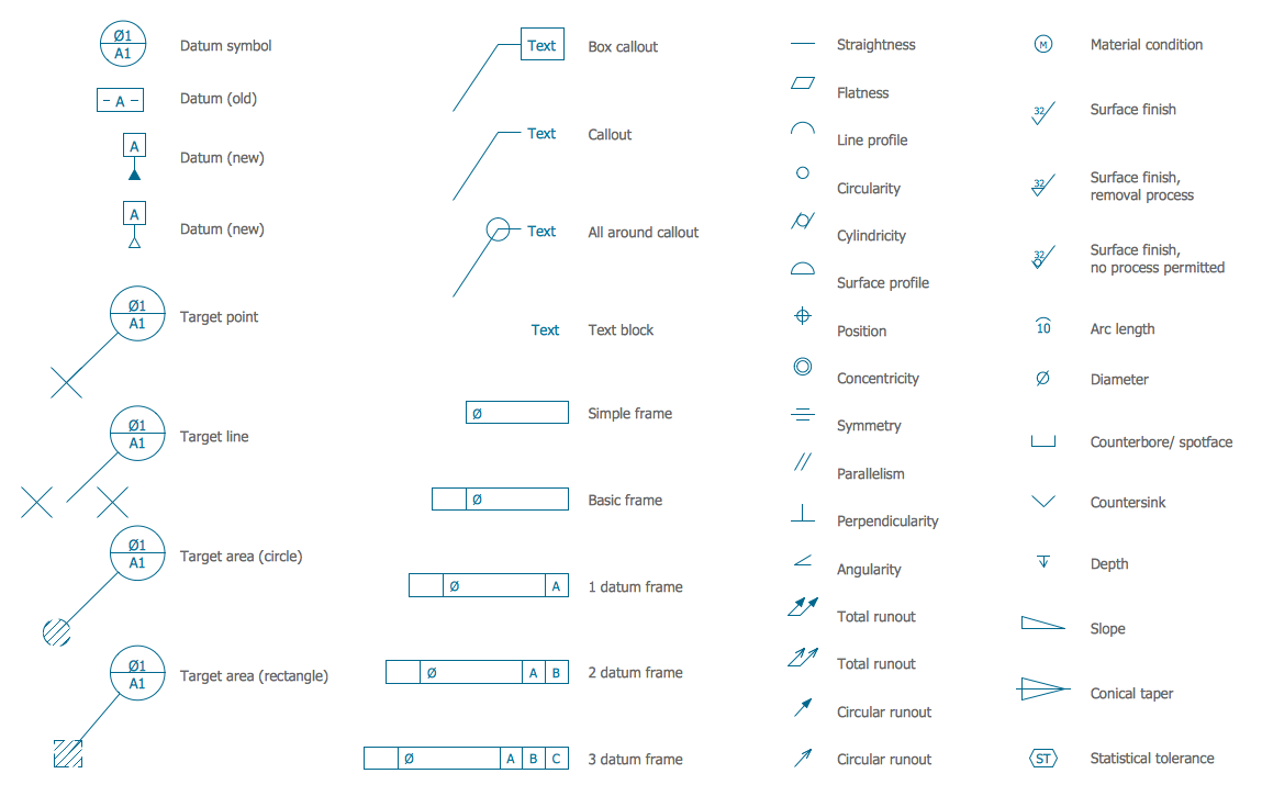
Conceptdraw diagram users have access to all of them and can insert them into the drawing by simply dragging and dropping: Note the comparison with the iso standards. Web mechanical engineering solution — 8 libraries are available with 602 commonly used mechanical drawing symbols in mechanical engineering solution, including libraries called bearings with 59 elements of roller and ball bearings,.

M&e Drawing Symbols Back To Basics Komseq
Working drawings are the set of technical drawings used during the manufacturing phase of a product. Web mechanical engineering solution — 8 libraries are available with 602 commonly used mechanical drawing symbols in mechanical engineering solution, including libraries called bearings with 59 elements of roller and ball bearings, shafts, gears, hooks, springs, spindles and keys; Because there is no large.

Mechanical Engineering Symbols Cadbull
Web a good design drawing can indicate all the details needed to produce a mechanical cnc milling part in an easy way. Web ask the assistant. In learning drafting, we will approach it from the perspective of manual drafting. 4 pdh a.bhatia continuing education and development, inc. Drawing views are simply the representation of your.

Mechanical Engineering Drawing Symbols Pdf Free Download at
Radius can be for the inside and outside curved surface on the part. After selecting many elements at once, all drawing annotations will move together. Web a good design drawing can indicate all the details needed to produce a mechanical cnc milling part in an easy way. Symbols or conventions used on the drawing and any additional information the designeror.

Mechanical Drawing Symbols from Mechanical Engineering — Welding
Web technical drawing symbols for mechanical engineering british standards institute staff technical drawings. For example, asme y14.5 and y14.100 are commonly used standards that define all of the symbols and drafting conventions used. If the drawing is made without either instruments or cad, it is called a freehand sketch. Users reported that in inventor drawing, moving text notes with symbol.

Mechanical Engineering Drawing Symbols Pdf Free Download at
This is a technical drawing title block example, and tells you the product designer, which in this case is essentra components. Web an engineering (or technical) drawing is a graphical representation of a part, assembly, system, or structure and it can be produced using freehand, mechanical tools, or computer methods. Note the comparison with the iso standards. Web the basic.
Mechanical Engineering Drawing Symbols Pdf Free Download at
Conceptdraw diagram users have access to all of them and can insert them into the drawing by simply dragging and dropping: Radius can be for the inside and outside curved surface on the part. For example, r6 means the circle has a radius of 6mm. “learning gd&t from scratch,” provided by keyence, walks you through the basics of geometric dimensioning.
Any Needed Height H 2 H H 2 H 60° 2 H Identification Letter Datum Feature Symbol Datum Target Symbol Target Point And.
Common abbreviations include ac (alternating current), dc (direct current), fab (fabrication), and ld (load). Working drawings are the set of technical drawings used during the manufacturing phase of a product. On the bottom of the title block, the mechanical engineering drawing provides other information that tells you more about the cap. 4 pdh a.bhatia continuing education and development, inc.
Because There Is No Large Space On A Drawing To Contain All The Text To Illustrate The Image, Abbreviations, And Symbols Are Often Used In Engineering Drawings To Communicate The Characteristics Of The Product To Be.
Web technical drawing symbols for mechanical engineering british standards institute staff technical drawings. Web mechanical engineering solution — 8 libraries are available with 602 commonly used mechanical drawing symbols in mechanical engineering solution, including libraries called bearings with 59 elements of roller and ball bearings, shafts, gears, hooks, springs, spindles and keys; The first tool in your engineering drawing toolbox is the drawing view. Conceptdraw diagram users have access to all of them and can insert them into the drawing by simply dragging and dropping:
Web Mechanical Engineering Solution Offers 602 Commonly Used Mechanical Drawing Symbols And Objects Which Are Professionally Designed And Grouped In 8 Libraries.
For example, asme y14.5 and y14.100 are commonly used standards that define all of the symbols and drafting conventions used. Web also called by various other names, such as engineering change order (eco), engineering change notice (ecn), drawing change notice (dcn), and so on. Most symbols have been in y14.5 since at least 1994. This is a technical drawing title block example, and tells you the product designer, which in this case is essentra components.
Web Ask The Assistant.
Web the technical engineering drawing abbreviations we outline here are the terms used in the manufacturing (include precision cnc machining and more) and inspection of parts and assemblies. If the drawing is made without either instruments or cad, it is called a freehand sketch. There are 7 aspects of the gd&t methodology that we will discuss, these include: Radius can be for the inside and outside curved surface on the part.