P Id Drawings
P Id Drawings - Through a p&id, you can get the following information: P&id is more complex than pfd and includes lots of details, because of th. 448k views 4 years ago #realpars #instrumentation. The mechanical and electrical details of a given system or process, Web p&id drawing is a schematic representation of instrumentations, control systems, and pipelines used in any process development plant. Web piping and instrumentation diagrams (p&ids) use specific symbols to show the connectivity of equipment, sensors, and valves in a control system. Web p&ids are a schematic illustration of the functional relationship of piping, instrumentation and system equipment components used in the field of instrumentation and control or automation. To create such a comprehensive design, start by listing the elements in a standard p&id. Web what is a p&id drawing? It uses symbols to represent process equipment such as sensors and controllers.
P&id is more complex than pfd and includes lots of details, because of th. Web in this video, you will learn the basics of piping and instrumentation diagrams (also called p&id drawings).#pipingandinstrumentation #processcontrol #instru. These symbols can represent actuators, sensors, and controllers and may be apparent in most, if not all, system diagrams. P&ids are used to develop guidelines and standards for facility operation. Web you will learn how to read p&id and pefs with the help of the actual plant drawing. Web piping and instrumentation diagrams (p&ids) use specific symbols to show the connectivity of equipment, sensors, and valves in a control system. P&id is more complex than pfd and includes lots of details. Visualize and understand your piping structures and processes. Reading real world examples | corso systems. Web all images are free to use!
Web what is a p&id drawing? P&id software built with engineers in mind. The shapes in this legend are representative of the functional relationship between piping, instrumentation, and system equipment units. It shows the equipment used in the process, and all of the signals required to measure and control the process. These symbols can represent actuators, sensors, and controllers and may be apparent in most, if not all, system diagrams. Web you will learn how to read p&id and pefs with the help of the actual plant drawing. 357k views 3 years ago basic instrumentation. Web piping and instrumentation diagrams (p&ids) use specific symbols to show the connectivity of equipment, sensors, and valves in a control system. P&id symbols refer to the standard notations and graphical representations used on piping and instrumentation diagrams (p&ids) to depict the components and systems involved in process flows within a facility. Web in this video, you will learn the basics of piping and instrumentation diagrams (also called p&id drawings).#pipingandinstrumentation #processcontrol #instru.

P & ID Diagram. How To Read P&ID Drawing Easily. Piping
Web p&id drawing, or piping and instrumentation diagrams, is like a special map that shows how pipes and instruments work together in factories and plants. Web the p&id, also known as the piping and instrumentation diagram, is an end to end schematic that displays major process details of a system. To create such a comprehensive design, start by listing the.
Piping & Instrumentation Diagrams (P&IDs) Punchlist Zero
To create such a comprehensive design, start by listing the elements in a standard p&id. P&id software built with engineers in mind. P&ids show operating conditions, major equipment, valves, and instrumentation required to run, monitor, and control a specific process. They are typically created by engineers who are designing a manufacturing process for a physical plant. Web p&ids are a.

Learn How to Read P&ID Drawings A Complete Guide
If you missed the first post in the series, p&id drawings 101, please review it first. Every symbol contains letters and a number. Our streamlined p&id software makes it easy for piping designers and electrical, mechanical, and process engineers to create accurate depictions of piping structures and other related components. Web piping and instrumentation diagrams (p&ids) use specific symbols to.

Piping and Instrumentation Documents Instrumentation Tools
P&id is more complex than pfd and includes lots of details, because of th. The shapes in this legend are representative of the functional relationship between piping, instrumentation, and system equipment units. 448k views 4 years ago #realpars #instrumentation. They are typically created by engineers who are designing a manufacturing process for a physical plant. Web piping and instrumentation diagrams,.

How to Read and Interpret Piping and Instrumentation Diagrams (P&ID
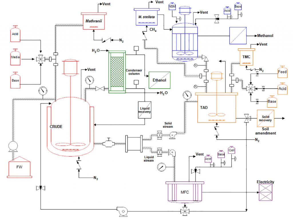
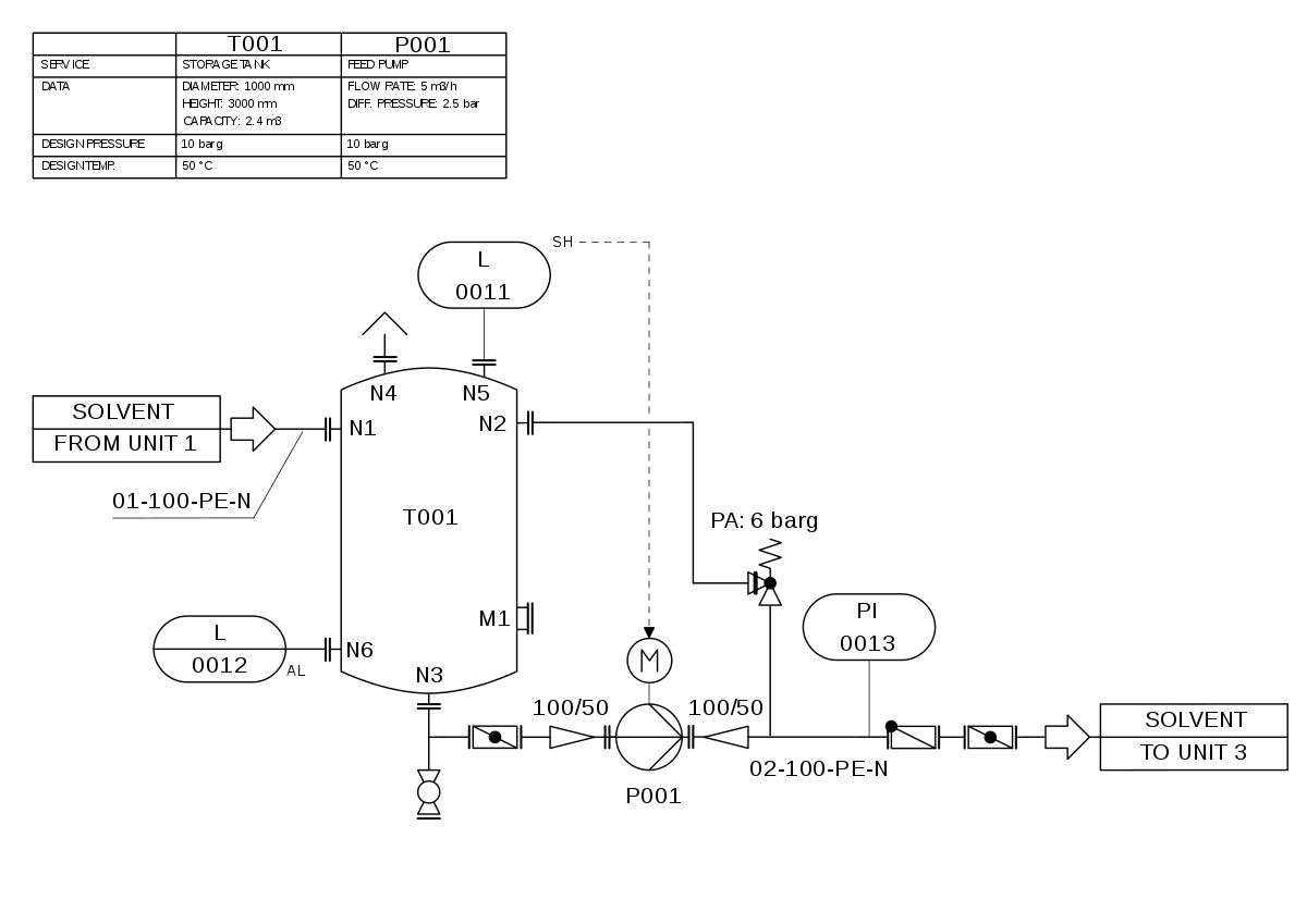
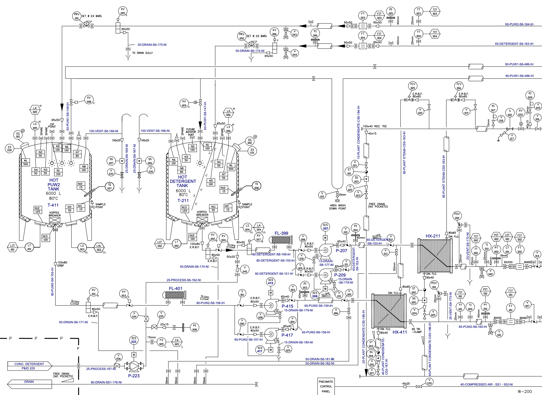
Web you will learn how to read p&id and pefs with the help of the actual plant drawing. Watch the video as it has. A link to download this p&id is given at the end of the page. Web a piping and instrumentation diagram (p&id or pid) is a detailed diagram in the process industry which shows the piping and.
Piping and Instrumentation Diagram P&ID Chemical Engineering Site
Piping & instrumentation diagram explained. Web p&id drawing is a schematic representation of instrumentations, control systems, and pipelines used in any process development plant. P&id is more complex than pfd and includes lots of details. It is the basic training document to explain the process details to operation guys, field engineers, and maintenance professionals. P&id, short for piping and instrumentation.
Reading P&ID Symbols A StepbyStep Guide GetReskilled
Web you will learn how to read p&id and pefs with the help of the actual plant drawing. Web a piping and instrumentation diagram, also called p&id, is a diagram used to show a graphical display of a complete system. Web p&id drawing, or piping and instrumentation diagrams, is like a special map that shows how pipes and instruments work.
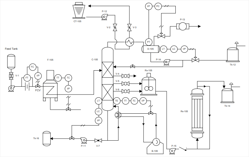
P&ID EXAMPLE
Web a piping and instrumentation diagram, also called p&id, is a diagram used to show a graphical display of a complete system. 357k views 3 years ago basic instrumentation. P&id is short for “piping and instrumentation diagram”. Reading real world examples | corso systems. Web p&id drawing, or piping and instrumentation diagrams, is like a special map that shows how.

Learn How to Read P&ID Drawings A Complete Guide
Web the p&id, also known as the piping and instrumentation diagram, is an end to end schematic that displays major process details of a system. Web you will learn how to read p&id and pefs with the help of the actual plant drawing. To create such a comprehensive design, start by listing the elements in a standard p&id. Watch the.
How to Read a P&ID Drawing Quickly and Easily Edraw Max
P&ids are used to develop guidelines and standards for facility operation. P&id, short for piping and instrumentation diagram, is a crucial visual representation in the field of engineering. Web all images are free to use! P&id is more complex than pfd and includes lots of details. A p&id uses simple graphics to represent complex processes and convey the flow of.
357K Views 3 Years Ago Basic Instrumentation.
P&id, short for piping and instrumentation diagram, is a crucial visual representation in the field of engineering. Web a piping and instrumentation diagram, also called p&id, is a diagram used to show a graphical display of a complete system. The shapes in this legend are representative of the functional relationship between piping, instrumentation, and system equipment units. Every symbol contains letters and a number.
They Are Typically Created By Engineers Who Are Designing A Manufacturing Process For A Physical Plant.
Piping & instrumentation diagram explained. Web p&id drawing, or piping and instrumentation diagrams, is like a special map that shows how pipes and instruments work together in factories and plants. Web what is a p&id drawing? The following diagrams will have more detail than in the first post.
A Link To Download This P&Id Is Given At The End Of The Page.
Web visual paradigm's p&id tool features a handy diagram editor that allows you to draw p&id diagrams, industrial diagrams, and schematics quickly and easily. Web all images are free to use! Web a piping and instrumentation diagram (p&id or pid) is a detailed diagram in the process industry which shows the piping and process equipment together with the instrumentation and control devices. Web piping and instrumentation diagrams, or p&ids, are used to create important documentation for process industry facilities.
These Symbols Can Represent Actuators, Sensors, And Controllers And May Be Apparent In Most, If Not All, System Diagrams.
It uses symbols to represent process equipment such as sensors and controllers. Your list should include all piping elements, including the order and placement of: 448k views 4 years ago #realpars #instrumentation. A p&id uses simple graphics to represent complex processes and convey the flow of material through a process.