Pid Drawing Symbols
Pid Drawing Symbols - Mechanical equipment named and listed numerically. You can also see the symbols for pneumatic, hydraulic, and capillary lines. It's quick, easy, and completely free. Process piping, sizes, and identification. Based on the industry and manufacturer, there is a wide variety of symbols. Process flow diagram (pfd) or process flow scheme (pfs) piping & instrument diagram (p&id) or process flow engineering scheme (pefs) process & instrument diagram. Solid lines represent pipes, with their size and material indicated by accompanying letters and numbers. Web piping and instrumentation diagrams (p&ids) use specific symbols to show the connectivity of equipment, sensors, and valves in a control system. P&id symbols refer to the standard notations and graphical representations used on piping and instrumentation diagrams (p&ids) to depict the components and systems involved in process flows within a facility. The p&id is the primary schematic drawing used for laying out a process control system’s installation.
Based on the industry and manufacturer, there is a wide variety of symbols. In the process industry, a standard set of symbols is. Looking for a library of common p&id symbols? Mechanical equipment named and listed numerically. Web piping and instrumentation diagrams (p&ids) use specific symbols to show the connectivity of equipment, sensors, and valves in a control system. These symbols can represent actuators, sensors, and controllers and may be. Solid lines represent pipes, with their size and material indicated by accompanying letters and numbers. Let us look at some of the most famous symbols suitable for smooth functioning across the industry. An engineer may also include specific details below the. Web what are p&id symbols.
Web the common p&id symbols are listed here: Web a piping and instrumentation diagram (p&id) is a graphic representation of a process system that includes the piping, vessels, control valves, instrumentation, and other process components and equipment in the system. Web piping and instrumentation diagrams (p&ids) use specific instrumentation symbols to show the connectivity of equipment, piping, sensors, and valves within a control system, and they are most commonly used in engineering. Web piping and instrument diagram standard symbols detailed documentation provides a standard set of shapes & symbols for documenting p&id and pfd, including standard shapes of instrument, valves, pump, heating exchanges, mixers, crushers, vessels, compressors, filters, motors and connecting shapes. Web common p&id symbols include: Web a p&id or process and instrumentation diagram provides a detailed graphical representation of the actual process system that includes the piping, equipment, valves, instrumentation, and other process components in the system. Here you can find what information is contained on a p&id. Web p&ids will typically include: Your list should include all piping elements, including the order and placement of: There is an article to introduce p&id symbols.
How to Read Oil and Gas P&ID Symbols Kimray
Web there's a huge variety of symbols, depending on industry and manufacturer, so we've created this guide to feature the most popular p&id symbols supported within our p&id software and is standardized for best practice across the industry. P&id symbols refer to the standard notations and graphical representations used on piping and instrumentation diagrams (p&ids) to depict the components and.

P&ID Symbols & Abbreviations Piping Analysis YouTube
Process flow diagram (pfd) or process flow scheme (pfs) piping & instrument diagram (p&id) or process flow engineering scheme (pefs) process & instrument diagram. Want to make a p&id of your own? Solid lines for process pipes, dashed lines for instrument signals, etc. Represented by a circle with a triangle pointing towards the center. Web the common p&id symbols are.
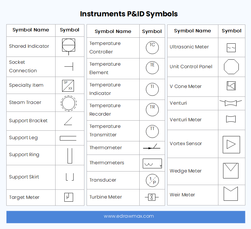
P&ID Symbols and Meanings EdrawMax Online
Pumps and tanks come in a variety of designs and shapes. Based on the industry and manufacturer, there is a wide variety of symbols. Scroll down or use the table of contents on the left to navigate this page and see the different p&id symbol types commonly used by engineers. Web what are p&id symbols? P&id symbols refer to the.
P & ID y PFD Drawing Symbols and Legend list (PFS & PEFS) Chad Wilken's
Web there's a huge variety of symbols, depending on industry and manufacturer, so we've created this guide to feature the most popular p&id symbols supported within our p&id software and is standardized for best practice across the industry. Pumps and tanks come in a variety of designs and shapes. Centrifugal pump, gear pump, diaphragm pump, etc. Represented by a circle.

How to Read and Interpret Piping and Instrumentation Diagrams (P&ID
Process flow diagram (pfd) or process flow scheme (pfs) piping & instrument diagram (p&id) or process flow engineering scheme (pefs) process & instrument diagram. In the process industry, a standard set of symbols is. Solid lines for process pipes, dashed lines for instrument signals, etc. Based on the industry and manufacturer, there is a wide variety of symbols. An engineer.

P&ID Symbols and Notation Lucidchart
Web piping and instrumentation diagrams (p&ids) use specific instrumentation symbols to show the connectivity of equipment, piping, sensors, and valves within a control system, and they are most commonly used in engineering. Web some commonly used symbols in p&id diagrams include: Like all other professional diagrams, p&ids has standard shapes and symbols. A diagram which shows the interconnection of process.
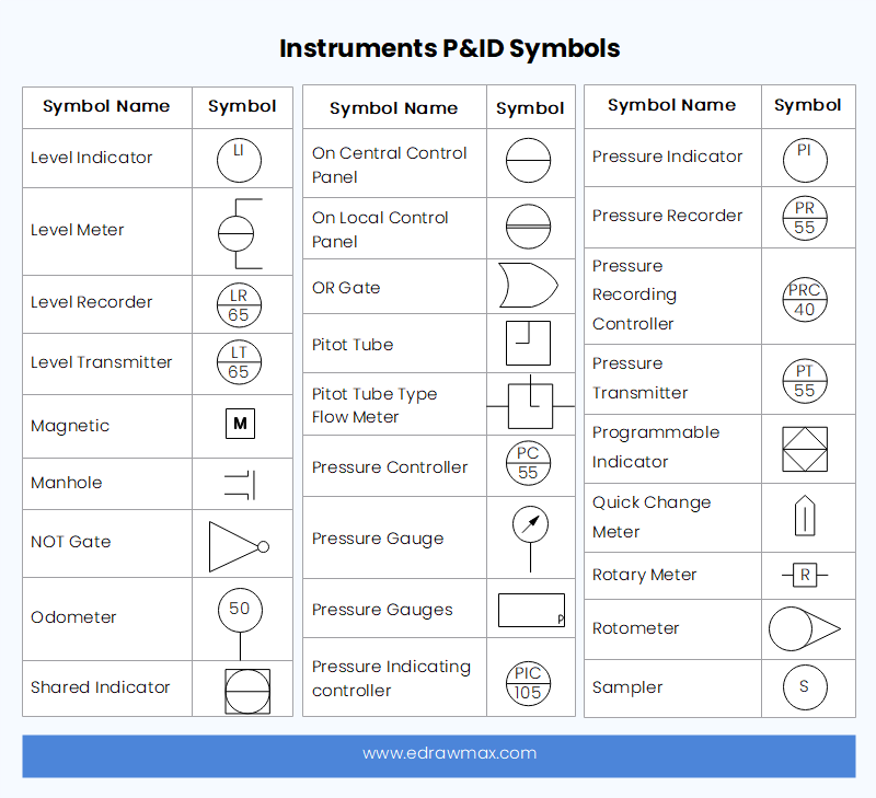
P&ID Symbols and Meanings EdrawMax Online
To create such a comprehensive design, start by listing the elements in a standard p&id. The p&id is the primary schematic drawing used for laying out a process control system’s installation. Centrifugal pump, gear pump, diaphragm pump, etc. As this diagram covers many types of diagrams as the variety in industries is vast, many symbols are required. These instrumentation symbols.

Your Instrumentation Common P&ID Symbols using in industries Tip for
Here you can find what information is contained on a p&id. These diagrams provide a map for the engineering system's design which is helpful to problem identification and solving. With download pdf for free. Web common p&id symbols include: Process flow diagram (pfd) or process flow scheme (pfs) piping & instrument diagram (p&id) or process flow engineering scheme (pefs) process.
P&ID Symbols and Meanings EdrawMax Online
An engineer may also include specific details below the. Web there's a huge variety of symbols, depending on industry and manufacturer, so we've created this guide to feature the most popular p&id symbols supported within our p&id software and is standardized for best practice across the industry. Web p&ids are a schematic illustration of the functional relationship of piping, instrumentation.

P&ID and PFD Drawing Symbols and Legend list (PFS & PEFS)
You can also see the symbols for pneumatic, hydraulic, and capillary lines. P&id is a graphical representation of the actual process plant using various symbols that represent actual equipment. In this video, you will learn. Web p&ids will typically include: Web piping and instrument diagram standard symbols detailed documentation provides a standard set of shapes & symbols for documenting p&id.
P&Id Diagrams Are Made With Specific And Standard Shapes And Symbols.
Web 363 common p&id symbols: Web p&ids are a schematic illustration of the functional relationship of piping, instrumentation and system equipment components used in the field of instrumentation and control or automation. Web there's a huge variety of symbols, depending on industry and manufacturer, so we've created this guide to feature the most popular p&id symbols supported within our p&id software and is standardized for best practice across the industry. Represented by a circle with a triangle pointing towards the center.
Based On The Industry And Manufacturer, There Is A Wide Variety Of Symbols.
Solid lines for process pipes, dashed lines for instrument signals, etc. Like all other professional diagrams, p&ids has standard shapes and symbols. To create such a comprehensive design, start by listing the elements in a standard p&id. As said earlier, it is more complex than pfd.
Storage Tanks, Reactors, Columns, Drums, Etc.
All components are represented using various p&id symbols. Dashed lines often indicate connections to existing systems or future installations. Solid lines represent pipes, with their size and material indicated by accompanying letters and numbers. These instrumentation symbols can represent actuators, sensors, and controllers.
These Symbols Can Represent Actuators, Sensors, And Controllers And May Be.
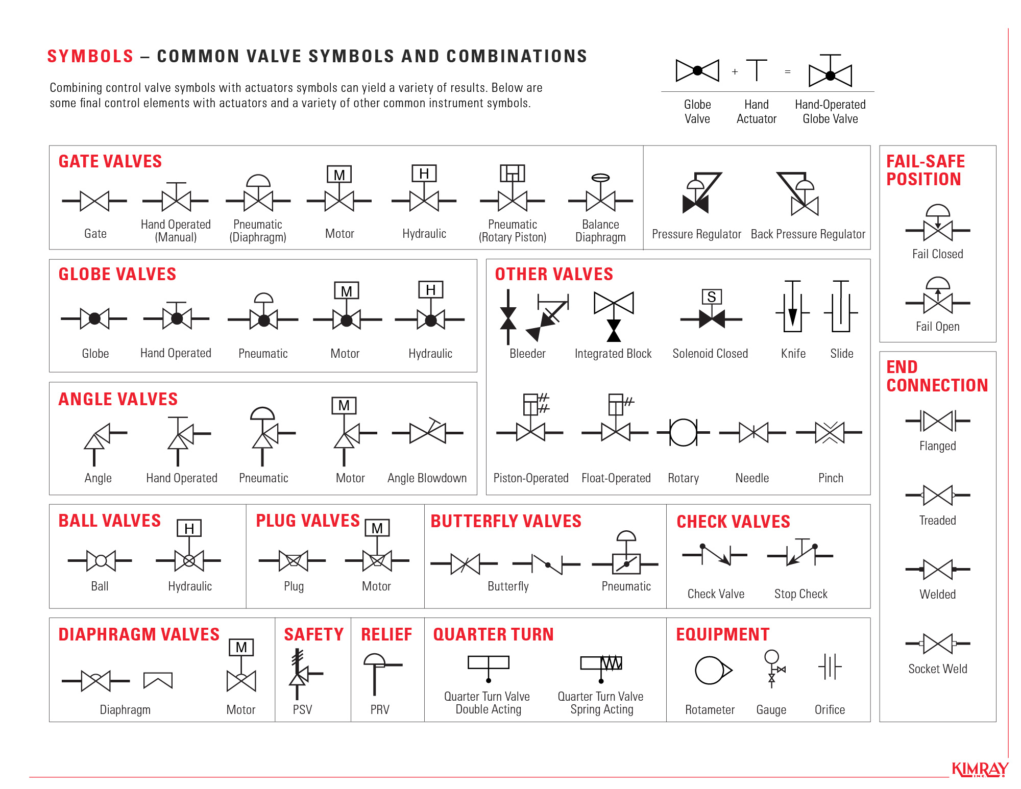
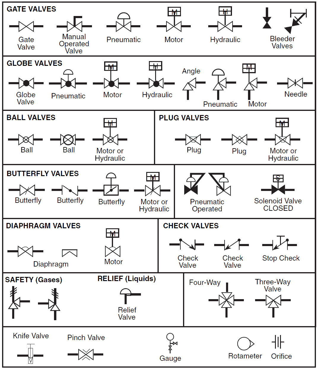
Web main process lines are shown as dark black lines, whereas minor lines are shown as thin black lines. In the process industry, a standard set of symbols is. P&id symbols for piping valves. Web p&id and pfd drawing symbols and legend list.