Pid Drawings
Pid Drawings - It includes all piping, instruments, valves, and equipment the system consists of. Piping & instrumentation diagram explained. The mechanical and electrical details of a given system or process, Piping and instrumentation diagrams, or p&ids, are used to create important documentation for process industry facilities. P&id is short for “piping and instrumentation diagram”. These symbols can represent actuators, sensors, and controllers and may be apparent in most, if not all, system diagrams. How it works •layout drawings: P&ids are used to develop guidelines and standards for facility operation. The piping and instrumentation diagram is also known as the process engineering flow scheme, pefs. Web p&id symbols refer to the standard notations and graphical representations used on piping and instrumentation diagrams (p&ids) to depict the components and systems involved in process flows within a facility.
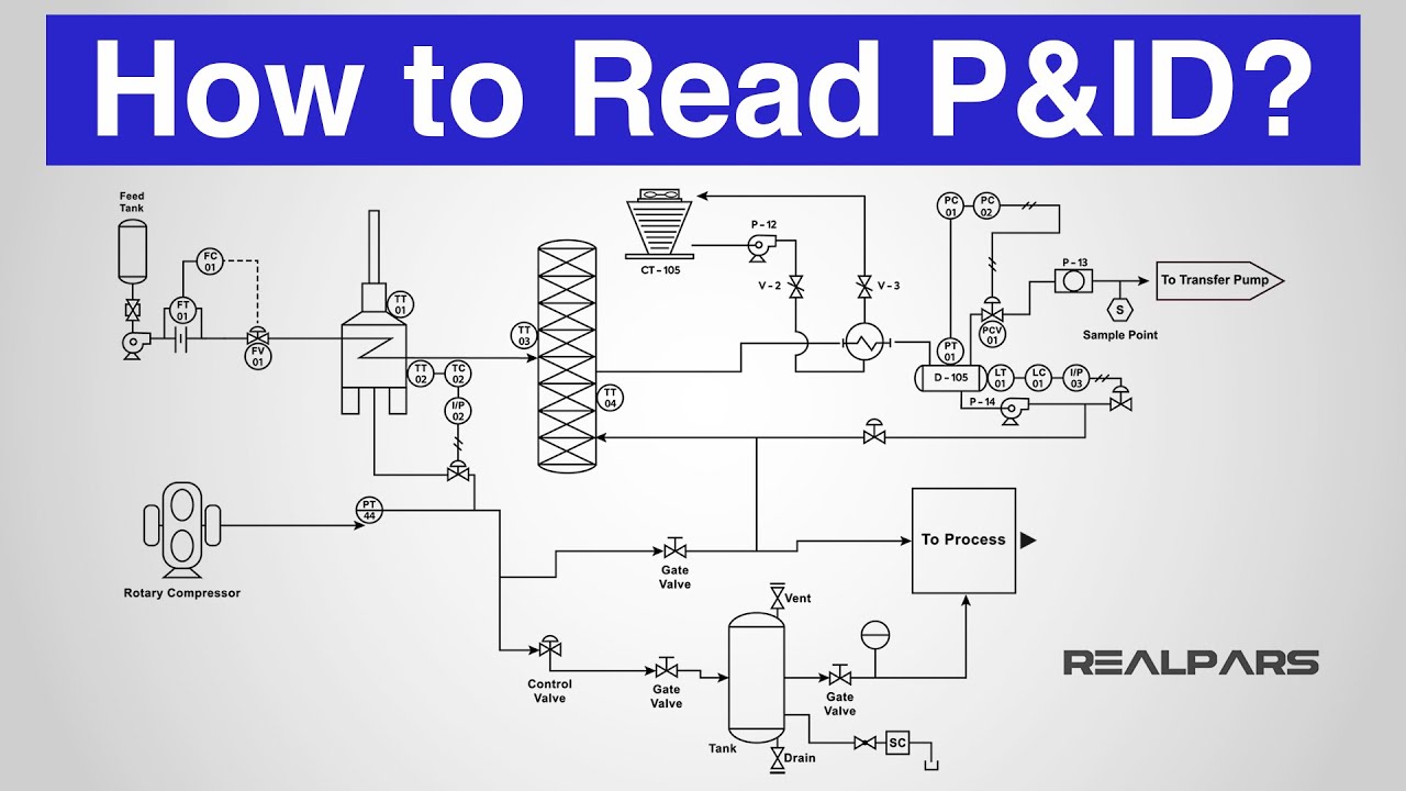
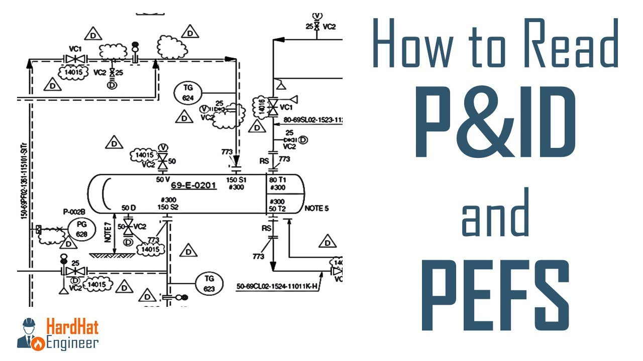
How it works •layout drawings: A piping and instrumentation diagram, or p&id, shows the piping and related components of a physical process flow. A process and instrumentation diagram (p & id) shows the process flow and interconnection of process equipment which is used control a process. How to read p&id drawing easily. 357k views 3 years ago basic. Web in this video, you will learn the basics of piping and instrumentation diagrams (also called p&id drawings).#pipingandinstrumentation #processcontrol #instru. Piping and instrumentation diagrams, or p&ids, are used to create important documentation for process industry facilities. The following diagrams will have more detail than in the first post. Web here, i have tried to explain p&id and pefs in an easy way. If you missed the first post in the series, p&id drawings 101, please review it first.
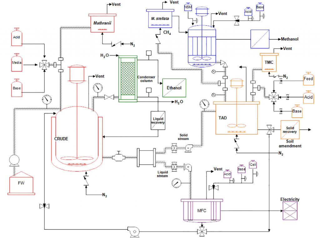
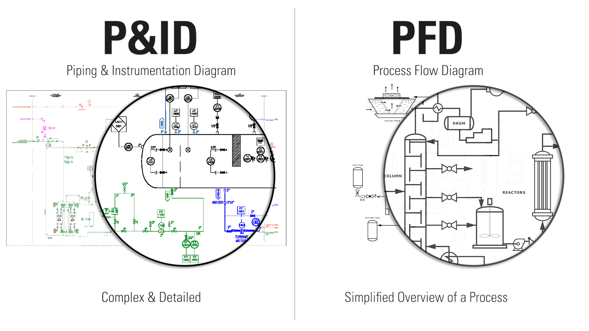
357k views 3 years ago basic. It serves as a vital tool in the process industry, forming the backbone of the design phase and providing a detailed layout of the plant's process. If you missed the first post in the series, p&id drawings 101, please review it first. P&ids are used to develop guidelines and standards for facility operation. Web p&id drawings 201: It is the basic training document to explain the process details to operation guys,. P&id is more complex than pfd and includes lots of details. Standard structures located on a p&id include storage tanks, surge tanks, pumps, heat exchangers, reactors, and distillation columns. Function and purpose of p&ids. Web the piping and instrumentation diagram (p&id) is a graphical representation of the actual process plant using various symbols that represent actual equipment.
How to Read a P&ID? (Piping & Instrumentation Diagram) YouTube
Through a p&id, you can get the following information: A p&id uses simple graphics to represent complex processes and convey the flow of material through a process. Remember that p&ids represent the hardware and software necessary to design, build, and run a process industry facility. (piping & instrumentation diagram) realpars. A process and instrumentation diagram (p & id) shows the.

Learn How to Read P&ID Drawings A Complete Guide (2023)
Web p & id diagram. P&id is more complex than pfd and includes lots of details. It shows the equipment used in the process, and all of the signals required to measure and control the process. Web in this video, you will learn the basics of piping and instrumentation diagrams (also called p&id drawings).#pipingandinstrumentation #processcontrol #instru. Web here, i have.
Piping & Instrumentation Diagrams (P&IDs) Punchlist Zero
A p&id uses simple graphics to represent complex processes and convey the flow of material through a process. (piping & instrumentation diagram) realpars. Web a piping and instrumentation diagram, also called p&id, is a diagram used to show a graphical display of a complete system. How to read p&id drawing easily. Web p&id drawing is a schematic representation of instrumentations,.

Piping and Instrumentation Documents Instrumentation Tools
Remember that p&ids represent the hardware and software necessary to design, build, and run a process industry facility. It shows the equipment used in the process, and all of the signals required to measure and control the process. It is the basic training document to explain the process details to operation guys,. Elements of a p&id • equipment & valves.

How to Read and Interpret Piping and Instrumentation Diagrams (P&ID
It serves as a vital tool in the process industry, forming the backbone of the design phase and providing a detailed layout of the plant's process. The following diagrams will have more detail than in the first post. How it works •layout drawings: Web p&id drawing is a schematic representation of instrumentations, control systems, and pipelines used in any process.
How to Read a P&ID Drawing Quickly and Easily Edraw Max
Web a piping and instrumentation diagram, also called p&id, is a diagram used to show a graphical display of a complete system. How it works •layout drawings: Through a p&id, you can get the following information: A p&id uses simple graphics to represent complex processes and convey the flow of material through a process. Web what is a p&id drawing?
How to Read Oil and Gas P&ID Symbols Kimray
The p & id includes every mechanical aspect of the plant except stream flows, pipe routing, pipe lengths, pipe fittings, supports, structure & foundations. Elements of a p&id • equipment & valves identified • instrumentation type &. Function and purpose of p&ids. Web the piping and instrumentation diagram (p&id) is a graphical representation of the actual process plant using various.

P & ID Diagram. How To Read P&ID Drawing Easily. Piping
It is also called as mechanical flow diagram (mfd). Remember that p&ids represent the hardware and software necessary to design, build, and run a process industry facility. It includes all piping, instruments, valves, and equipment the system consists of. The mechanical and electrical details of a given system or process, Web piping and instrumentation diagrams (p&ids) use specific symbols to.
How to Read P&ID Drawing A Complete Tutorial YouTube
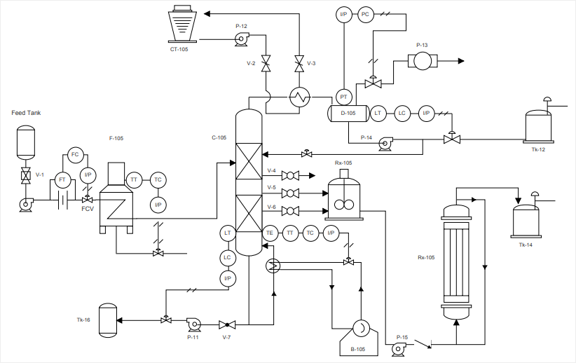
The following diagrams will have more detail than in the first post. It uses symbols to represent process equipment such as sensors and controllers. The mechanical and electrical details of a given system or process, You will learn how to read p&id and pefs with the help of the actual plant drawing. Web p&id, short for piping and instrumentation diagram,.
Learn How to Read P&ID Drawings A Complete Guide (2023)
Web what is a p&id drawing? It serves as a vital tool in the process industry, forming the backbone of the design phase and providing a detailed layout of the plant's process. Web p&id drawings 201: The p & id includes every mechanical aspect of the plant except stream flows, pipe routing, pipe lengths, pipe fittings, supports, structure & foundations..
Web P&Id Drawings 201:
It serves as a blueprint that outlines the interconnection of piping, equipment, instrumentation, and controls within a process system. Web p&id symbols refer to the standard notations and graphical representations used on piping and instrumentation diagrams (p&ids) to depict the components and systems involved in process flows within a facility. Web what is a p&id drawing? You will learn how to read p&id and pefs with the help of the actual plant drawing.
These Symbols Can Represent Actuators, Sensors, And Controllers And May Be Apparent In Most, If Not All, System Diagrams.
It is the basic training document to explain the process details to operation guys,. The mechanical and electrical details of a given system or process, It serves as a vital tool in the process industry, forming the backbone of the design phase and providing a detailed layout of the plant's process. Standard structures located on a p&id include storage tanks, surge tanks, pumps, heat exchangers, reactors, and distillation columns.
P&Id Is Short For “Piping And Instrumentation Diagram”.
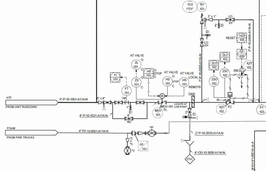
Elements of a p&id • equipment & valves identified • instrumentation type &. Web what is p & id? Remember that p&ids represent the hardware and software necessary to design, build, and run a process industry facility. In the second post of our p&id series, we will be working through an example of a simplified drawing.
Web Piping And Instrumentation Diagrams (P&Ids) Use Specific Symbols To Show The Connectivity Of Equipment, Sensors, And Valves In A Control System.
Piping & instrumentation diagram explained. Web p&id drawing is a schematic representation of instrumentations, control systems, and pipelines used in any process development plant. Draw p&id diagrams online in the browser with google docs. A p&id uses simple graphics to represent complex processes and convey the flow of material through a process.