Pipeline Drawings
Pipeline Drawings - Web a piping isometric drawing is a technical drawing that depicts a pipe spool or a complete pipeline using an isometric representation. Web the technique called section views is a very important aspect of design and documentation. A piping single line drawing (or piping one line drawing) is a piping drawing that shows the size and location of pipes, fittings and valves. Web pipe culverts and endwalls. It is used to improve the visualization and clarity of new designs, clarify multiview drawings, reveal interior features of parts, and facilitate the dimensioning of drawings. These highly structured drawings provide a comprehensive 3d representation of the arrangement, dimensions, and connections of pipes within a system. It is drawn to scale so the relationships of the aforementioned are correctly shown. Piping joint types, weld types. Web the san jose sharks have won the 2024 nhl draft lottery and will pick no. Pythagoras theorem (for rolling movement of pipe) let’s first.
Web published may 6, 2024 updated may 7, 2024. Web pipeline isometric drawings are crucial visual representations in the fields of engineering and construction. P&ids are foundational to the maintenance and modification of the process that it graphically represents. Web here are the post positions and morning line odds for the 2024 preakness: How to read iso drawings. Web in this article, we will explore all those piping drawings that are required to execute piping work. These highly structured drawings provide a comprehensive 3d representation of the arrangement, dimensions, and connections of pipes within a system. We are concluding our first pipefitter series run with a video on how to draw isometric drawings. Isometric drawings are commonly used in industries such as the oil and gas industry, petrochemical industry, and plumbing for planning, design, construction, and pipeline maintenance. Web various symbols are used to indicate piping components, instrumentation, equipments in engineering drawings such as piping and instrumentation diagram (p&id), isometric drawings, plot plan, equipment layout, welding drawings etc.
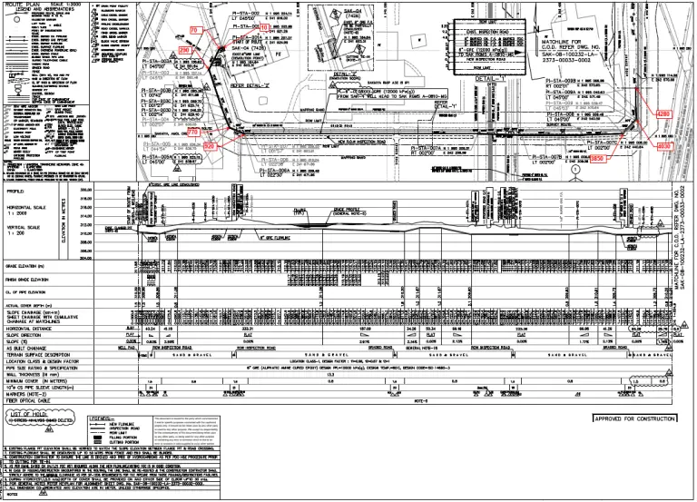
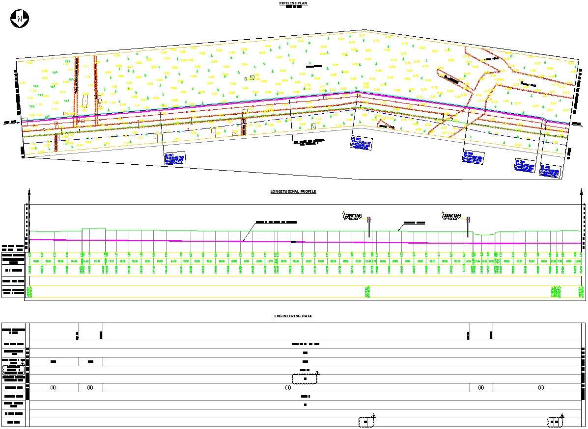
1 overall at the draft in las vegas this summer. Web we're part of the front row joe's, said sharon anderson of etowah, tennessee at the front of the line. Web pipeline isometrics are detailed drawings used in engineering and design to represent the 3d layout of a pipeline system on a 2d surface. For mechanical drawings section views are used to reveal interior features of an object when hidden. General arrangement drawing (gad)/piping plan drawing. Alignment drawings provide a clear and concise visual representation of the pipeline route, making it easier for stakeholders to understand the proposed pipeline route and identify any potential conflicts or obstacles. These drawings are impelled to supply a more detailed and authentic representation, emphasising the pipes, valves and other components’ shape, size and. It is used to improve the visualization and clarity of new designs, clarify multiview drawings, reveal interior features of parts, and facilitate the dimensioning of drawings. Piping isometric drawing consists of three sections. How to read iso drawings.

Piping Isometric Drawings The Piping Engineering World
Web easy isometric is the first pipe isometric drawing app that helps users make detailed isometric drawings in the field and without the need for tedious reference materials. Accurate drawing symbols, callouts, precise coordinates, and elevations provide intricate information to the fabricator. Web the san jose sharks have won the 2024 nhl draft lottery and will pick no. Reading tips,.
Understanding Pipeline Alignment Drawings Benefits, Reading, and
Function and purpose of p&ids. Pipe sizes 18” to 72”, all skews, 2:1 & 3:1 slopes). It’s most commonly used in the engineering field. Web the process of drafting isometric drawings for a pipeline system involves referencing the arrangements of the pipelines, sections, and elevation drawings during its development. Figure 1.6 directional anchor nps 8 to nps 12.
Pipeline Isometric Drawings Explained NDT Techniques & Interpretation
Discover the essentials of piping isometrics, including how they simplify complex piping systems for construction, maintenance, and documentation purposes. 1 overall at the draft in las vegas this summer. The types of drawings developed by pipe drafters and the engineering groups that use them are reviewed. It is used to improve the visualization and clarity of new designs, clarify multiview.

How to read isometric drawing piping dadver
Web © 2024 google llc. Process flow diagram (pfd) piping and instrumentation drawing (p&id). These highly structured drawings provide a comprehensive 3d representation of the arrangement, dimensions, and connections of pipes within a system. No more tedious material tracking when creating a pipe isometric drawing. We are concluding our first pipefitter series run with a video on how to draw.

How to read piping isometric drawing, Pipe fitter training, Watch the
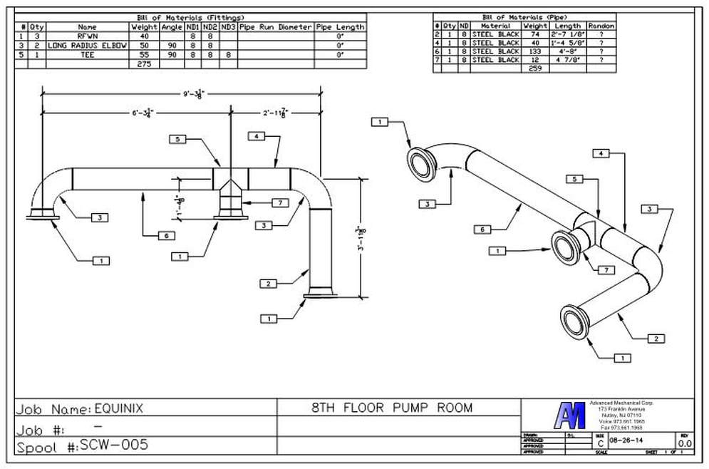
This chapter is an overview of the pipe drafting and design profession. Web pipe culverts and endwalls. The drawing axes of the isometrics intersect at an angle of 60°. Web a piping isometric drawing provides all the required information like: Web the technique called section views is a very important aspect of design and documentation.
What Is Piping Plan Drawing Design Talk
Web a piping isometric drawing provides all the required information like: Web various symbols are used to indicate piping components, instrumentation, equipments in engineering drawings such as piping and instrumentation diagram (p&id), isometric drawings, plot plan, equipment layout, welding drawings etc. This chapter is an overview of the pipe drafting and design profession. It lists the various facility types where.

Isometric Piping Drawings Advenser
This chapter is an overview of the pipe drafting and design profession. No more tedious material tracking when creating a pipe isometric drawing. How to read iso drawings. These drawings provide a detailed 3d illustration of a piping system, offering a comprehensive view of its components, dimensions, and. It is drawn to scale so the relationships of the aforementioned are.

Piping orthographic to isometric drawing exercises masoppalm
Web posted in design engineering. Web the process of drafting isometric drawings for a pipeline system involves referencing the arrangements of the pipelines, sections, and elevation drawings during its development. It is the most important deliverable of piping engineering department. Web published may 6, 2024 updated may 7, 2024. Application areas are plumbing, civil, process, and transportation.
Pipeline layout plan AutoCAD drawing ,cad file Cadbull
Acquisition of right of way (row) acquisition of land for repeater stations and block valves. Pythagoras theorem (for rolling movement of pipe) let’s first. It is used to improve the visualization and clarity of new designs, clarify multiview drawings, reveal interior features of parts, and facilitate the dimensioning of drawings. Discover the essentials of piping isometrics, including how they simplify.

What is Piping Isometric drawing? How to Read Piping Drawing? ALL
It lists the various facility types where pipe drafting and design is applied and the types of companies that employ pipe drafters. Accurate drawing symbols, callouts, precise coordinates, and elevations provide intricate information to the fabricator. A piping single line drawing (or piping one line drawing) is a piping drawing that shows the size and location of pipes, fittings and.
It’s Most Commonly Used In The Engineering Field.
Accurate drawing symbols, callouts, precise coordinates, and elevations provide intricate information to the fabricator. Web there are several benefits of a pipeline alignment drawing or alignment sheet, including: This chapter is an overview of the pipe drafting and design profession. It is drawn to scale so the relationships of the aforementioned are correctly shown.
Pythagoras Theorem (For Rolling Movement Of Pipe) Let’s First.
No more tedious material tracking when creating a pipe isometric drawing. With that top overall pick, the sharks will get a new franchise. The drawing axes of the isometrics intersect at an angle of 60°. Web we're part of the front row joe's, said sharon anderson of etowah, tennessee at the front of the line.
Web But At Age 57, And Better Known For His Roles In Such Projects As The Hangover Films And The Mike Tyson Mysteries Tv Series Over The Last 19 Years, Tyson Has Raised Concerns That He’s Making A.
Function and purpose of p&ids. For mechanical drawings section views are used to reveal interior features of an object when hidden. Web easy isometric is the first pipe isometric drawing app that helps users make detailed isometric drawings in the field and without the need for tedious reference materials. Web various symbols are used to indicate piping components, instrumentation, equipments in engineering drawings such as piping and instrumentation diagram (p&id), isometric drawings, plot plan, equipment layout, welding drawings etc.
Web Posted In Design Engineering.
Web a piping isometric drawing provides all the required information like: A piping single line drawing (or piping one line drawing) is a piping drawing that shows the size and location of pipes, fittings and valves. There are usually five types of piping drawings that are prepared to communicate various information in a simple and easy way. Web in this article, we will explore all those piping drawings that are required to execute piping work.