Pipework Drawing Symbols
Pipework Drawing Symbols - And abbreviations conventional plan symbols. Web pipe drawings are much different from specific weld symbols but they do have a similar relationship from part to symbol. To request the symbols, simply complete this short form and you'll be taken to a page where you can download the symbols (as zip files). Example of rolling angle calculation: Web a piping isometric drawing provides all the required information like: Web piping symbols, also known as pipe drawings, are a set of symbols used in metal fabrication drawings to represent the various types of pipes and fittings used in industrial piping systems. This part of bs 1553 specifies graphical symbols for use in flow and piping diagrams for process plant. Piping and component descriptions with size, quantity, and material codes. Web the symbols on these diagrams represent various elements, including: These symbols are used to indicate the type of connection, the direction of flow, and the size of the pipe.
Piping and component descriptions with size, quantity, and material codes. Lines that indicate the direction of flow, along with specifications about the pipe size, material, and number. Web symbols sheet 2 [c:\cadd\sample plans\a sheets\sym(sample).dgn. Whenever you start reading a piping drawing or document, you can see many abbreviations on these drawings/documents. Symbols are shown in black lines. 1.2 this set of standard symbols is intended for use on piping system diagrammatics and arrangements for ships. What are the plumbing symbols. Many abbreviations are common and are regularly used in the drawings but few of the abbreviation are new and unique for a particular drawing. Show any project specific abbreviations and symbols here Project number sheet project name project number a3 nps pmis no.
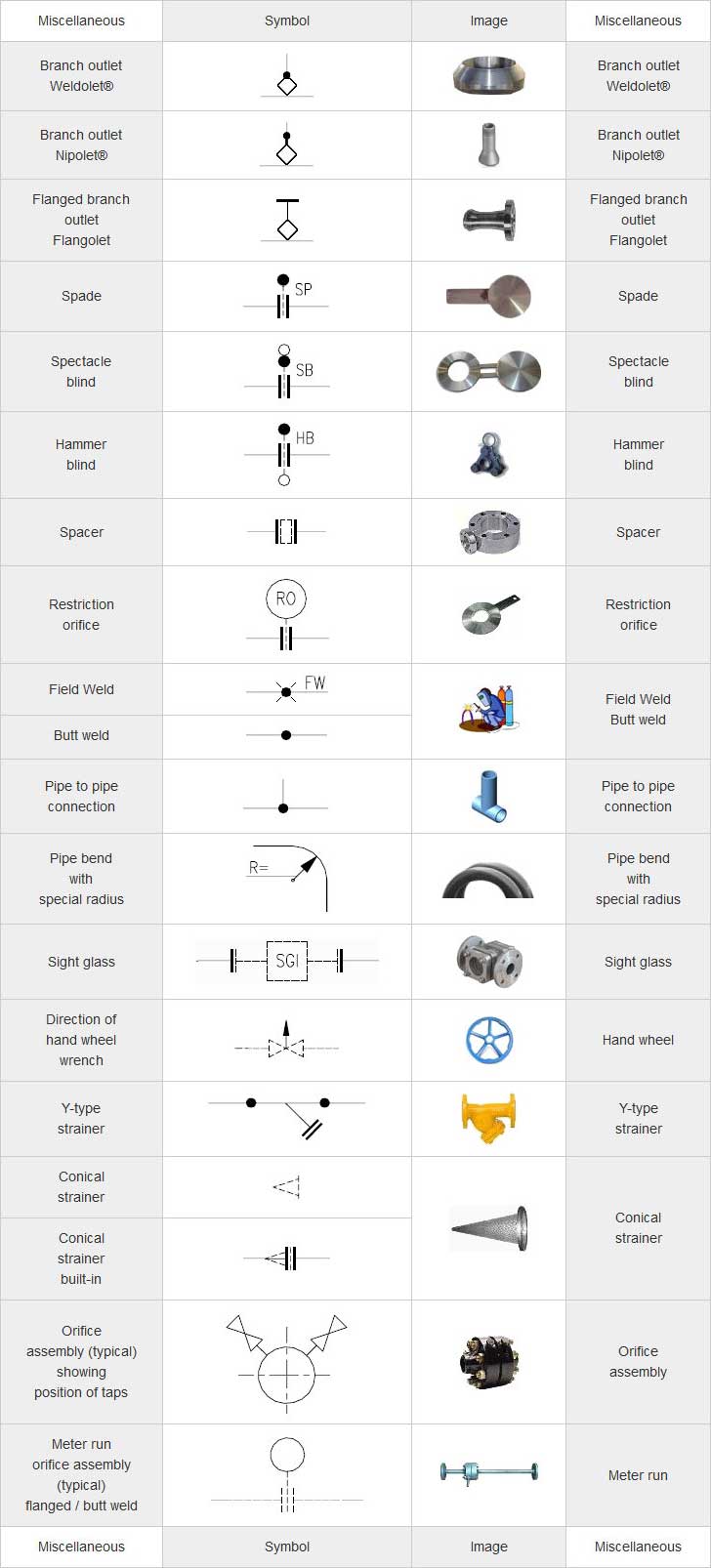
Web piping layout drawings abbreviations and legends. Piping symbol chart for piping isometric or p&id. Web a piping isometric drawing is a technical drawing that depicts a pipe spool or a complete pipeline using an isometric representation. Example of rolling angle calculation: By using these standardized symbols, engineers and operators can communicate effectively and ensure consistency in the design and operation of process systems. What are the plumbing symbols. Web various symbols are used to indicate piping components, instrumentation, equipments in engineering drawings such as piping and instrumentation diagram (p&id), isometric drawings, plot plan, equipment layout, welding drawings etc. Web piping isometric drawing is an isometric representation of single pipe line in a plant. This part of bs 1553 specifies graphical symbols for use in flow and piping diagrams for process plant. It is done for the supply of water, provision of drainage passages, and prevention from pipeline destruction.
Pipe Symbols Interpretation of Metal Fab Drawings
Pipe drawings are much different from specific weld symbols but they do have a similar relationship from part to symbol. Web more than 2000 vector piping and instrumentation diagram symbols are provided including ductwork symbols, valves, pumps, motors, blowers, chillers, tanks, logistics, production process symbols, hvac symbols, and much more. Web symbols sheet 2 [c:\cadd\sample plans\a sheets\sym(sample).dgn. Some individuals will.

Piping Isometric Drawing Symbols Pdf at Explore
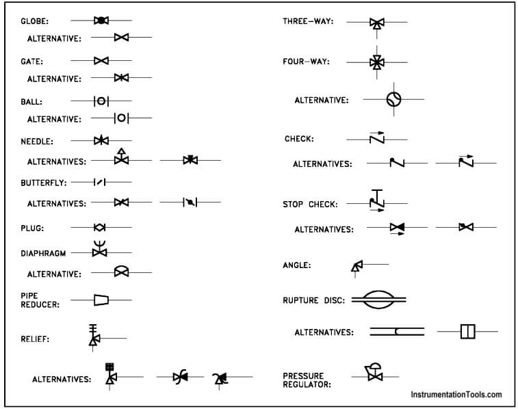
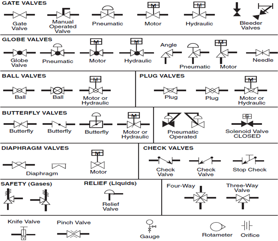
Web more than 2000 vector piping and instrumentation diagram symbols are provided including ductwork symbols, valves, pumps, motors, blowers, chillers, tanks, logistics, production process symbols, hvac symbols, and much more. To read and understand engineering fluid diagrams and prints, usually referred to as p&ids, an individual must be familiar with the basic symbols. Web pipe drawings are much different from.

How to read piping isometric drawing pdf fleetlio
Web a graphical symbols for piping systems and plant. How to read piping isometric drawing? These schemes contain numerous symbols, symbols, and abbreviations representing numerous components, such as pipes, valves, pumps, and. Pipe drawings are much different from specific weld symbols but they do have a similar relationship from part to symbol. Web piping symbols, also known as pipe drawings,.

Piping Isometric Drawings The Piping Engineering World
Piping fabrication work is based on isometric drawings. Web the symbols on these diagrams represent various elements, including: What are the plumbing symbols. Web more than 2000 vector piping and instrumentation diagram symbols are provided including ductwork symbols, valves, pumps, motors, blowers, chillers, tanks, logistics, production process symbols, hvac symbols, and much more. 1.2 this set of standard symbols is.
Piping and Instrumentation Symbols Instrumentation Tools
Some individuals will not see these in their line of work but it is important to be aware of them. Web a piping isometric drawing provides all the required information like: Feature of piping drawing symbols. What are the plumbing symbols. It is the most important deliverable of piping engineering department.
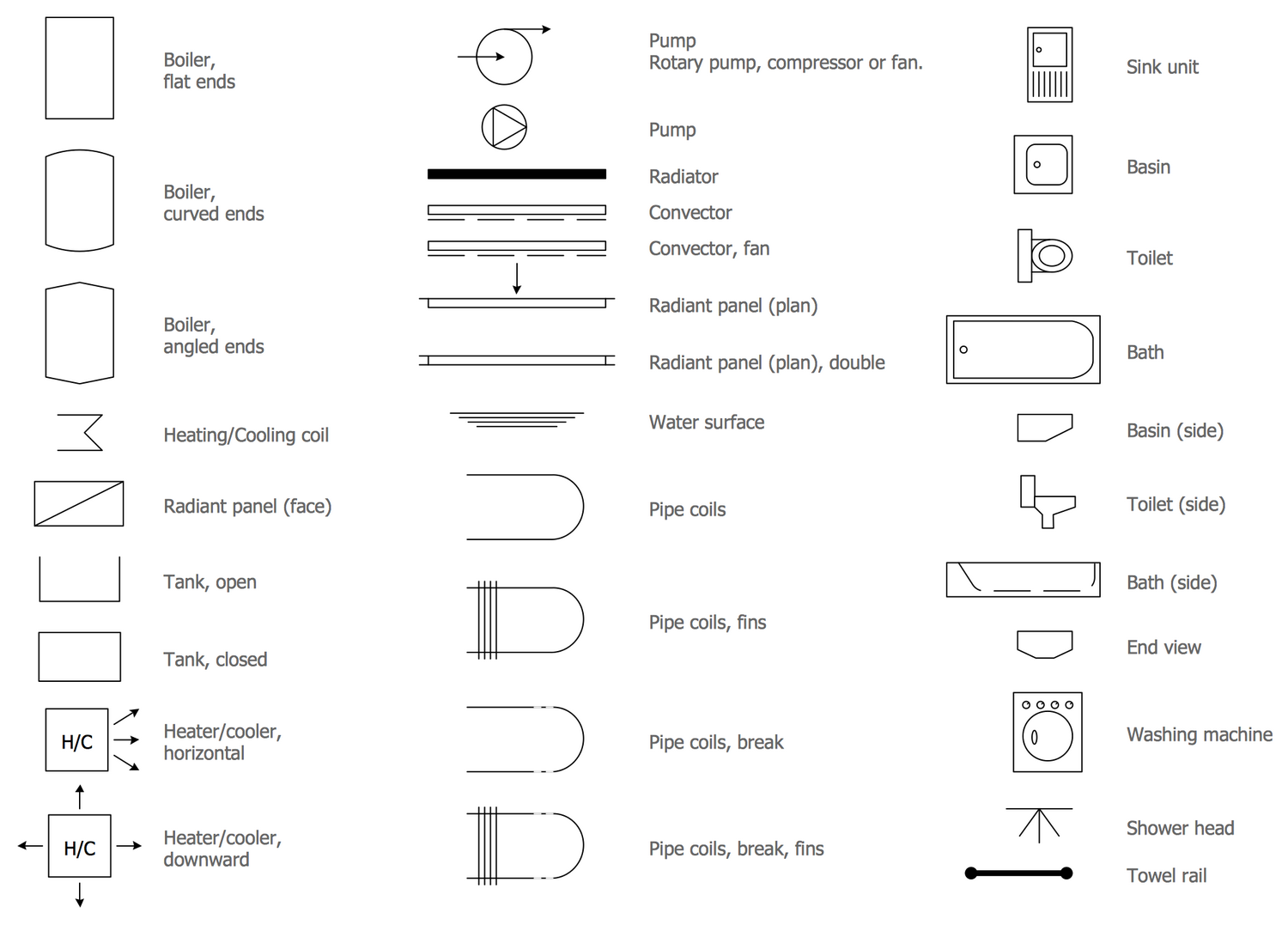
Piping Schematic Symbols Pdf
Web plumbing and piping diagrams are project blueprints that include drawings and symbols of essential plumbing processes and components, including: These symbols are used to indicate the type of connection, the direction of flow, and the size of the pipe. Symbols are shown in black lines. By using these standardized symbols, engineers and operators can communicate effectively and ensure consistency.

What is Piping Isometric drawing? How to Read Piping Drawing? ALL
What is piping isometric drawing? Piping symbol chart for piping isometric or p&id. 1.2 this set of standard symbols is intended for use on piping system diagrammatics and arrangements for ships. Web pipe drawings are much different from specific weld symbols but they do have a similar relationship from part to symbol. It is done for the supply of water,.
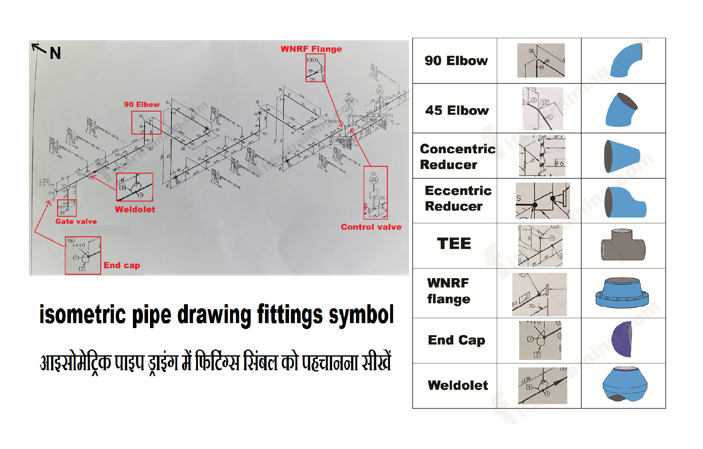
isometric pipe drawing fittings symbol Fitter training
Web the symbols on these diagrams represent various elements, including: It is the most important deliverable of piping engineering department. Feature of piping drawing symbols. Pipe and instrument diagram symbols. Web plumbing and piping diagrams are project blueprints that include drawings and symbols of essential plumbing processes and components, including:
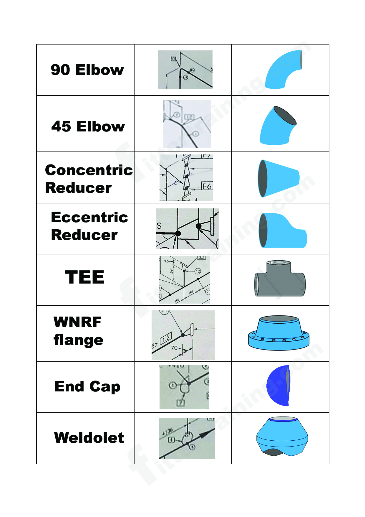
isometric pipe drawing fittings symbol Fitter training
It is done for the supply of water, provision of drainage passages, and prevention from pipeline destruction. Pipe drawings are much different from specific weld symbols but they do have a similar relationship from part to symbol. Web the symbols on these diagrams represent various elements, including: What are the plumbing symbols. The drawing axes of the isometrics intersect at.
Piping Isometric Drawing Symbols Pdf at Explore
To request the symbols, simply complete this short form and you'll be taken to a page where you can download the symbols (as zip files). Project number sheet project name project number a3 nps pmis no. Symbols are shown in black lines. Web a piping isometric drawing provides all the required information like: Lines that indicate the direction of flow,.
To Request The Symbols, Simply Complete This Short Form And You'll Be Taken To A Page Where You Can Download The Symbols (As Zip Files).
Web piping layout drawings abbreviations and legends. Piping joint types, weld types. Show any project specific abbreviations and symbols here This part of bs 1553 specifies graphical symbols for use in flow and piping diagrams for process plant.
1.2 This Set Of Standard Symbols Is Intended For Use On Piping System Diagrammatics And Arrangements For Ships.
The drawing axes of the isometrics intersect at an angle of 60°. Plumbing plan is connecting pipelines in the walls of a building and underground. These symbols are used to indicate the type of connection, the direction of flow, and the size of the pipe. To read and understand engineering fluid diagrams and prints, usually referred to as p&ids, an individual must be familiar with the basic symbols.
Pipe And Instrument Diagram Symbols.
Web a graphical symbols for piping systems and plant. Lighter lines show connected pipe, and are not parts of the symbols. Some individuals will not see these in their line of work but it is important to be aware of them. Checkout list of such symbols given below.
Web Symbols Sheet 2 [C:\Cadd\Sample Plans\A Sheets\Sym(Sample).Dgn.
Lines that indicate the direction of flow, along with specifications about the pipe size, material, and number. How to read piping isometric drawing? Web piping and instrument diagram standard symbols detailed documentation provides a standard set of shapes & symbols for documenting p&id and pfd, including standard shapes of instrument, valves, pump, heating exchanges, mixers, crushers, vessels, compressors, filters, motors and connecting shapes. Piping and component descriptions with size, quantity, and material codes.