Piping Isometric Drawing Symbols
Piping Isometric Drawing Symbols - Web isometric drawing symbols for piping valves. How to draw isometric piping drawings. 1.3 where graphical symbols are required for an item or equipment not covered by this practice, the form and character of the symbol will be left. The direction should be selected so as to facilitate easy checking of isometrics with ga. This information is conveyed through the use of callouts and notes placed on the drawing. Isolating, venting & draining symbols for ease of maintenance; An isometric drawing is a type of pictorial drawing in which three sides of an object can be seen in one view. No attempt is made to represent a pipe’s actual size or pound rating graphically. Web piping symbols serve as the alphabet of isometric drawings, with each symbol representing a specific component, similar to words in a language. Web what is an isometric drawing?
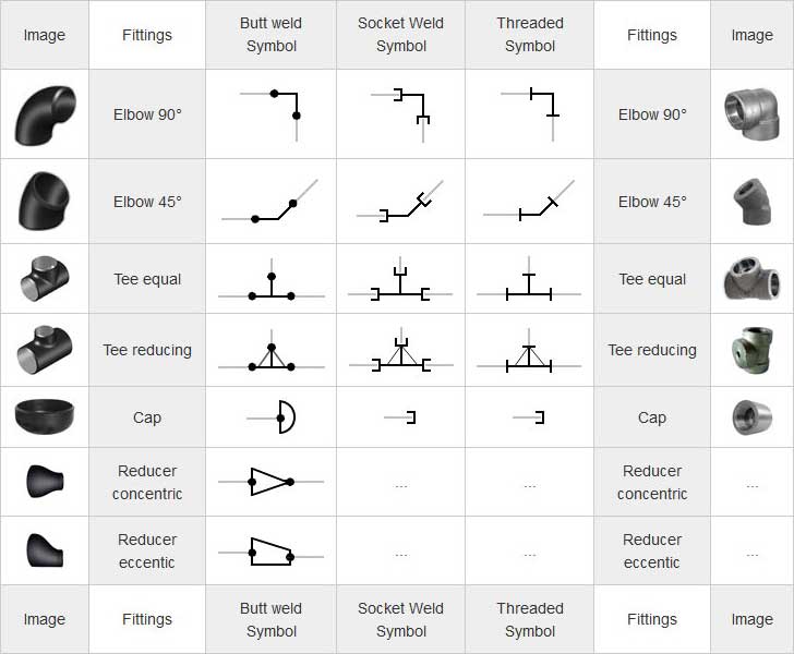
An isometric drawing is a type of pictorial drawing in which three sides of an object can be seen in one view. 1.2 this set of standard symbols is intended for use on piping system diagrammatics and arrangements for ships. Precise representation of piping components and their relationships, ensuring compatibility and functionality. In the world of industrial projects, precision and accuracy are. Web isometric symbols for piping fittings. Symbols are shown in black lines. No attempt is made to represent a pipe’s actual size or pound rating graphically. Piping isometric dwg symbols designed just for you in autocad. All of our vector cad models are of the highest quality. Web piping and instrument diagram standard symbols detailed documentation provides a standard set of shapes & symbols for documenting p&id and pfd, including standard shapes of instrument, valves, pump, heating exchanges, mixers, crushers, vessels, compressors, filters, motors and connecting shapes.
The direction should be selected so as to facilitate easy checking of isometrics with ga. Web isometric symbols for piping fittings. No attempt is made to represent a pipe’s actual size or pound rating graphically. Piping isometric dwg symbols designed just for you in autocad. Comprehensive depiction of fittings, connections, and supports, aiding in the construction and maintenance of the system. Web piping and instrument diagram standard symbols detailed documentation provides a standard set of shapes & symbols for documenting p&id and pfd, including standard shapes of instrument, valves, pump, heating exchanges, mixers, crushers, vessels, compressors, filters, motors and connecting shapes. Lighter lines show connected pipe, and are not parts of the symbols. Various symbols are used to indicate piping components, instrumentation, equipments in engineering drawings such as piping and instrumentation diagram (p&id), isometric drawings, plot plan, equipment layout, welding drawings etc. Isolating, venting & draining symbols for ease of maintenance; Web pipeline isometrics are detailed drawings used in engineering and design to represent the 3d layout of a pipeline system on a 2d surface.

How to Read Basic Piping Isometric Drawings Piping Analysis YouTube
All of our vector cad models are of the highest quality. Symbols are shown in black lines. Web pipeline isometrics are detailed drawings used in engineering and design to represent the 3d layout of a pipeline system on a 2d surface. Web the following information must be included in piping isometric drawings: Isometric drawings are commonly used in industries such.

Piping Isometric DWG Symbols Free Download Drawing in CAD
Web the following information must be included in piping isometric drawings: Lines that indicate the direction of flow, along with specifications about the pipe size, material, and number. Checkout list of such symbols given below. This information is conveyed through the use of callouts and notes placed on the drawing. Web piping symbols serve as the alphabet of isometric drawings,.
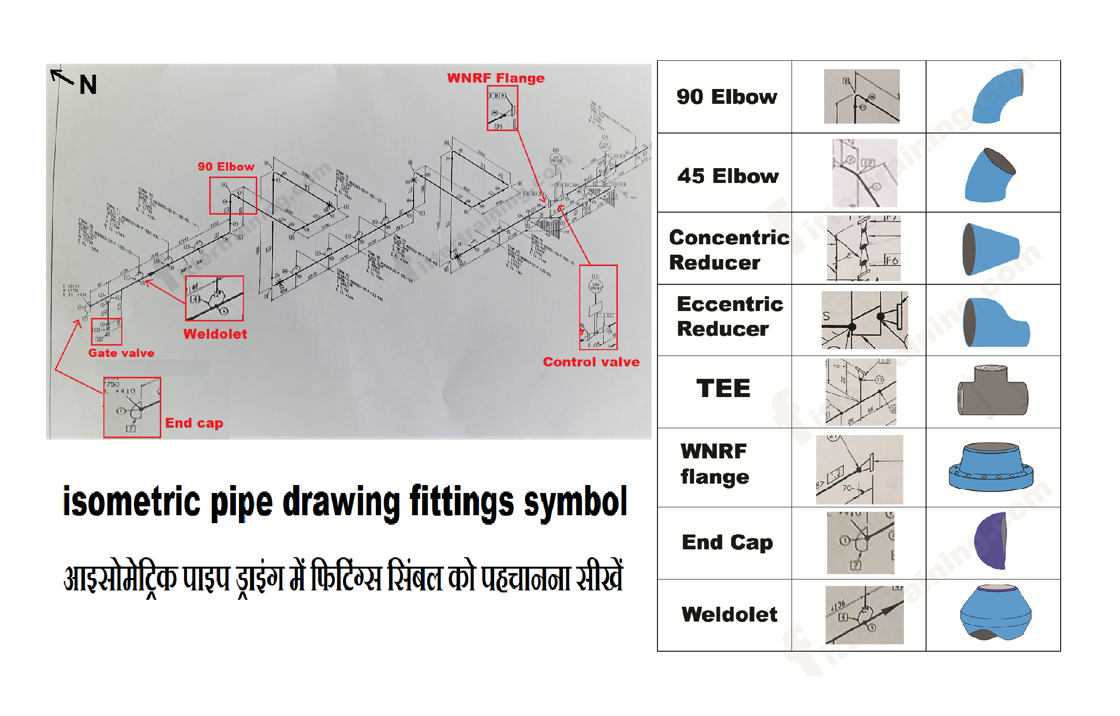
isometric pipe drawing fittings symbol Fitter training
Visit our website and download all the drawings you like. Web isometric symbols for fittings, flanges, and valves represent all sizes of pipe. In the world of industrial projects, precision and accuracy are. The direction should be selected so as to facilitate easy checking of isometrics with ga. Standards and conventions for valve status;

Valves Symbols used in P&ID and Piping Isometric drawings YouTube
Lighter lines show connected pipe, and are not parts of the symbols. Standards and conventions for valve status; 1.2 this set of standard symbols is intended for use on piping system diagrammatics and arrangements for ships. Checkout list of such symbols given below. In the world of industrial projects, precision and accuracy are.

Basic Piping Isometric Symbols Piping Analysis YouTube
Isometric drawings are commonly used in industries such as the oil and gas industry, petrochemical industry, and plumbing for planning, design, construction, and pipeline maintenance. Standards and conventions for valve status; Comprehensive depiction of fittings, connections, and supports, aiding in the construction and maintenance of the system. Web isometric symbols for piping fittings. This information is conveyed through the use.

Sample isometric drawing for piping klowebcam
An isometric drawing is a type of pictorial drawing in which three sides of an object can be seen in one view. Web how to read piping isometric drawing symbols. Reference number of pefs (p&id), ga drawings, line numbers, the direction of flow, and insulation tracing. 1.2 this set of standard symbols is intended for use on piping system diagrammatics.

Isometric drawing for piping lmsop
Piping isometric dwg symbols designed just for you in autocad. The direction should be selected so as to facilitate easy checking of isometrics with ga. Symbols are shown in black lines. In the world of industrial projects, precision and accuracy are. Precise representation of piping components and their relationships, ensuring compatibility and functionality.

Piping Isometric Drawings The Piping Engineering World
Web piping symbols serve as the alphabet of isometric drawings, with each symbol representing a specific component, similar to words in a language. All of our vector cad models are of the highest quality. Isolating, venting & draining symbols for ease of maintenance; Various symbols are used to indicate piping components, instrumentation, equipments in engineering drawings such as piping and.
Piping Coordination System Mechanical symbols for Isometric drawings
Web piping symbols serve as the alphabet of isometric drawings, with each symbol representing a specific component, similar to words in a language. All of our vector cad models are of the highest quality. Web pipeline isometrics are detailed drawings used in engineering and design to represent the 3d layout of a pipeline system on a 2d surface. Web isometric.
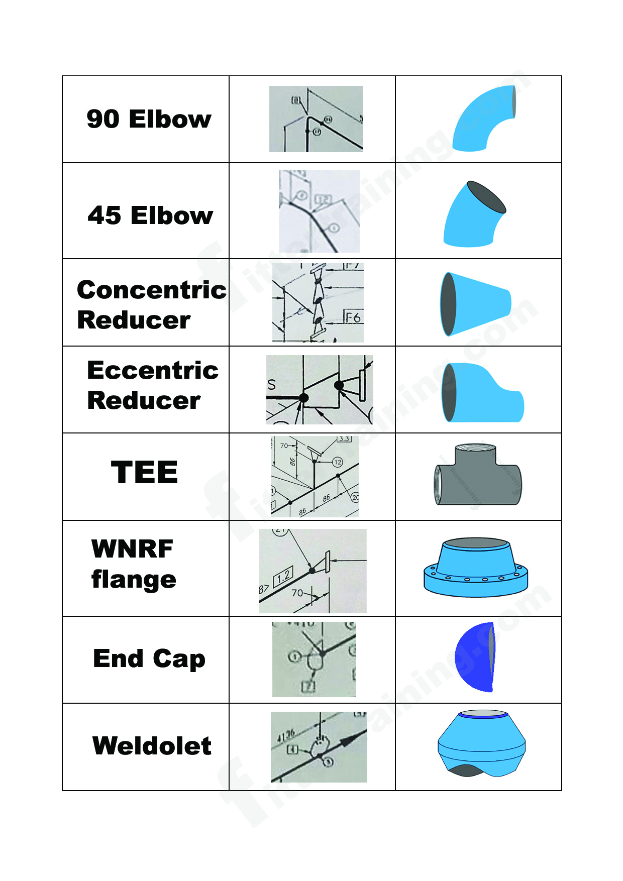
isometric pipe drawing fittings symbol Fitter training
Web the following information must be included in piping isometric drawings: Web how to read piping isometric drawing symbols. Various symbols are used to indicate piping components, instrumentation, equipments in engineering drawings such as piping and instrumentation diagram (p&id), isometric drawings, plot plan, equipment layout, welding drawings etc. Web pipeline isometrics are detailed drawings used in engineering and design to.
Web Pipeline Isometrics Are Detailed Drawings Used In Engineering And Design To Represent The 3D Layout Of A Pipeline System On A 2D Surface.
The direction should be selected so as to facilitate easy checking of isometrics with ga. Web piping symbols serve as the alphabet of isometric drawings, with each symbol representing a specific component, similar to words in a language. Visit our website and download all the drawings you like. Web piping and instrument diagram standard symbols detailed documentation provides a standard set of shapes & symbols for documenting p&id and pfd, including standard shapes of instrument, valves, pump, heating exchanges, mixers, crushers, vessels, compressors, filters, motors and connecting shapes.
Precise Representation Of Piping Components And Their Relationships, Ensuring Compatibility And Functionality.
How to draw isometric piping drawings. Web the symbols on these diagrams represent various elements, including: An isometric drawing is a type of pictorial drawing in which three sides of an object can be seen in one view. Various symbols are used to indicate piping components, instrumentation, equipments in engineering drawings such as piping and instrumentation diagram (p&id), isometric drawings, plot plan, equipment layout, welding drawings etc.
No Attempt Is Made To Represent A Pipe’s Actual Size Or Pound Rating Graphically.
Although piping isometrics are not drawn to scale, it should be drawn proportionally. Standards and conventions for valve status; Reference number of pefs (p&id), ga drawings, line numbers, the direction of flow, and insulation tracing. Lighter lines show connected pipe, and are not parts of the symbols.
Web The Following Information Must Be Included In Piping Isometric Drawings:
Web isometric symbols for fittings, flanges, and valves represent all sizes of pipe. Comprehensive depiction of fittings, connections, and supports, aiding in the construction and maintenance of the system. Isometric drawings are commonly used in industries such as the oil and gas industry, petrochemical industry, and plumbing for planning, design, construction, and pipeline maintenance. Web basic piping isometric symbols :