Pneumatic Schematic Drawings
Pneumatic Schematic Drawings - Web pneudraw allows you to draw pneumatic circuits quickly and easily. When it succeeds, it’s invisible. Web this white paper examines pneumatic design best practices, and then presents four basic pneumatic circuits (table 1) commonly used in machine automation. Web a pneumatic circuit diagram is a schematic representation of how pneumatic components, such as valves, tanks, and pumps, are connected to form a. Outline of pneumatic circuit diagram creation program. Web it is desired to move a 200lb load 12 inches at a rate of 20 cycles per minute. Web hydraulic p&id diagrams and schematics, hydraulic piping, hydraulic diagrams, hydraulic symbols, hydraulic line diagrams, pneumatic p&id, pneumatic symbols. Design elements valves and ings retract resistor check valve application symbol flow direction. Web free downloadable symbol library in svg, png, jpg, dxf & dwg formats. It provides a clear and concise.
For additional information on pneumatic and hydraulic schematics click on the following links: When it succeeds, it’s invisible. Web a pneumatic system schematic diagram is a visual representation of the various components and connections in a pneumatic system. What is needed is a group of pneumatic component symbols that will provide the circuit designer, both novice and professional, with a viable shorthand that will save. Web free downloadable symbol library in svg, png, jpg, dxf & dwg formats. Web helpful reference web pages. Web this white paper examines pneumatic design best practices, and then presents four basic pneumatic circuits (table 1) commonly used in machine automation. Design elements valves and ings retract resistor check valve application symbol flow direction. Web compressed air schematic symbols play a crucial role in understanding and designing pneumatic systems. These symbols provide a standardized representation of various.
Web helpful reference web pages. Web compressed air schematic symbols play a crucial role in understanding and designing pneumatic systems. Web pneumatic symbols were principally created to identify components on circuit design diagrams, but they can also be used on the components themselves. Design elements valves and ings retract resistor check valve application symbol flow direction. Web a pneumatic circuit diagram is a schematic representation of how pneumatic components, such as valves, tanks, and pumps, are connected to form a. Outline of pneumatic circuit diagram creation program. Only when the design fails does it draw attention to itself; When it succeeds, it’s invisible. For additional information on pneumatic and hydraulic schematics click on the following links: Using a 2” bore cylinder, about 64 psi is required to move the load.
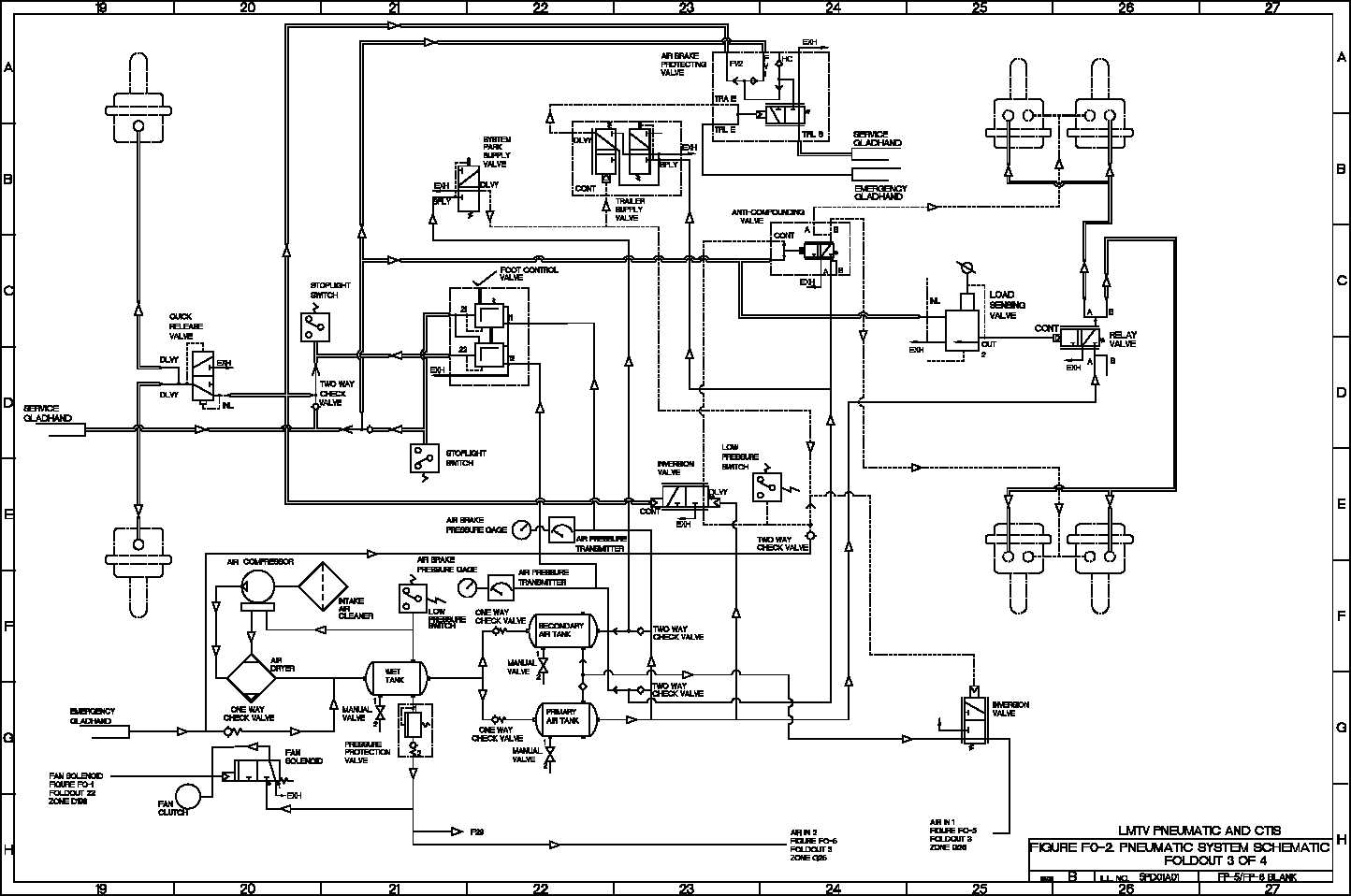
pneumatic system schematic TM92320365202_1363
Web a basic pneumatic circuit diagram illustrates the fundamental components and their connections, providing a blueprint for the system’s operation. What is needed is a group of pneumatic component symbols that will provide the circuit designer, both novice and professional, with a viable shorthand that will save. Web it is desired to move a 200lb load 12 inches at a.

Schematic representation of pneumatic system Download Scientific Diagram
Web a basic pneumatic circuit diagram illustrates the fundamental components and their connections, providing a blueprint for the system’s operation. For additional information on pneumatic and hydraulic schematics click on the following links: Web hydraulic p&id diagrams and schematics, hydraulic piping, hydraulic diagrams, hydraulic symbols, hydraulic line diagrams, pneumatic p&id, pneumatic symbols. All the symbols you need to design your..

Pneumatic circuit schematic diagram of multicylinder single
Web a pneumatic system schematic diagram is a visual representation of the various components and connections in a pneumatic system. All the symbols you need to design your. Using a 2” bore cylinder, about 64 psi is required to move the load. Web free downloadable symbol library in svg, png, jpg, dxf & dwg formats. With the new online release,.

3 Way Pneumatic Valve Schematic Diagram IOT Wiring Diagram
Web compressed air schematic symbols play a crucial role in understanding and designing pneumatic systems. For additional information on pneumatic and hydraulic schematics click on the following links: Beside pneumatic symbols the tool. With the new online release, it is easier than ever to draw your circuits. Pneumatic circuit diagrams in practice usually consist of several circuits, that means you.

Pneumatic System Schematic Diagram
Web it is desired to move a 200lb load 12 inches at a rate of 20 cycles per minute. Outline of pneumatic circuit diagram creation program. Web a pneumatic system schematic diagram is a visual representation of the various components and connections in a pneumatic system. What is needed is a group of pneumatic component symbols that will provide the.
Pneumatic Circuit Design Airlane Pneumatics Limited
When it succeeds, it’s invisible. Pneumatic circuit diagrams in practice usually consist of several circuits, that means you have a lots of valves and associated actuators. Web helpful reference web pages. Web a pneumatic system schematic diagram is a visual representation of the various components and connections in a pneumatic system. Web a basic pneumatic circuit diagram illustrates the fundamental.
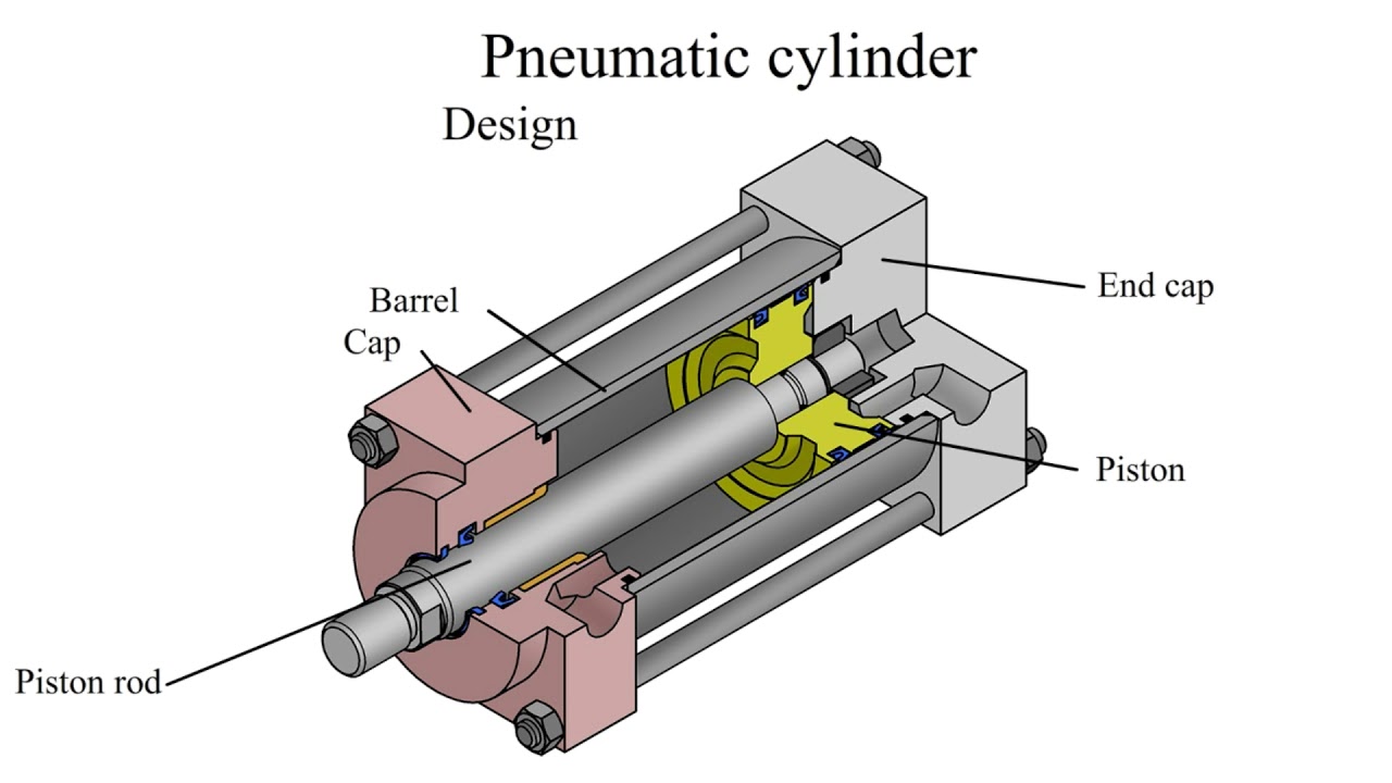
How does a pneumatic cylinder work? Pneumatic cylinder design YouTube
When it succeeds, it’s invisible. Web this white paper examines pneumatic design best practices, and then presents four basic pneumatic circuits (table 1) commonly used in machine automation. Web reading pneumatic schematic symbols. What is needed is a group of pneumatic component symbols that will provide the circuit designer, both novice and professional, with a viable shorthand that will save..

Pneumatic Circuit Design Airlane Pneumatics Limited
Web pneudraw allows you to draw pneumatic circuits quickly and easily. Web reading pneumatic schematic symbols. Web a pneumatic circuit diagram is a schematic representation of how pneumatic components, such as valves, tanks, and pumps, are connected to form a. Web pneumatic symbols were principally created to identify components on circuit design diagrams, but they can also be used on.
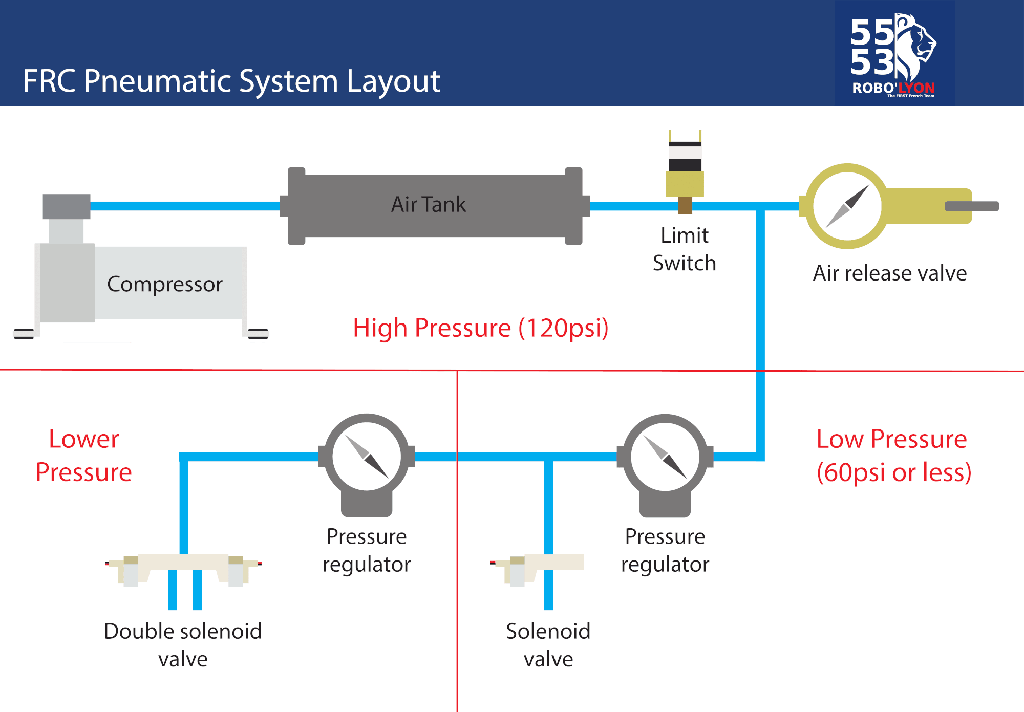
FRC Pneumatic System Diagram Control System Chief Delphi
Web it is desired to move a 200lb load 12 inches at a rate of 20 cycles per minute. Web a basic pneumatic circuit diagram illustrates the fundamental components and their connections, providing a blueprint for the system’s operation. When it succeeds, it’s invisible. Web helpful reference web pages. Pneumatic circuit diagrams in practice usually consist of several circuits, that.

Schematic Pneumatic Diagram Download drawings, blueprints, Autocad
Design elements valves and ings retract resistor check valve application symbol flow direction. Using a 2” bore cylinder, about 64 psi is required to move the load. Web a pneumatic circuit diagram is a schematic representation of how pneumatic components, such as valves, tanks, and pumps, are connected to form a. Web helpful reference web pages. Web this white paper.
Web A Basic Pneumatic Circuit Diagram Illustrates The Fundamental Components And Their Connections, Providing A Blueprint For The System’s Operation.
Web compressed air schematic symbols play a crucial role in understanding and designing pneumatic systems. Only when the design fails does it draw attention to itself; Web it is desired to move a 200lb load 12 inches at a rate of 20 cycles per minute. It provides a clear and concise.
Web A Pneumatic System Schematic Diagram Is A Visual Representation Of The Various Components And Connections In A Pneumatic System.
Outline of pneumatic circuit diagram creation program. For additional information on pneumatic and hydraulic schematics click on the following links: Web this white paper examines pneumatic design best practices, and then presents four basic pneumatic circuits (table 1) commonly used in machine automation. Web reading pneumatic schematic symbols.
Web Pneumatic Symbols Were Principally Created To Identify Components On Circuit Design Diagrams, But They Can Also Be Used On The Components Themselves.
These symbols provide a standardized representation of various. Using a 2” bore cylinder, about 64 psi is required to move the load. Web pneudraw allows you to draw pneumatic circuits quickly and easily. All the symbols you need to design your.
Web Hydraulic P&Id Diagrams And Schematics, Hydraulic Piping, Hydraulic Diagrams, Hydraulic Symbols, Hydraulic Line Diagrams, Pneumatic P&Id, Pneumatic Symbols.
When it succeeds, it’s invisible. What is needed is a group of pneumatic component symbols that will provide the circuit designer, both novice and professional, with a viable shorthand that will save. Web free downloadable symbol library in svg, png, jpg, dxf & dwg formats. Web a pneumatic circuit diagram can be easily created by using the database for pneumatic equipment drawing symbols.