Substation Drawing
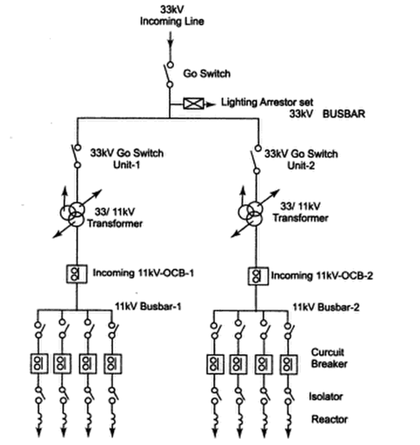
Substation Drawing - Asce manuals and reports on engineering practice no. The gang operated switch (g.o. Switch, the 11 kv line is brought to the indoor substation as underground cable.it is fed to the hv side of the. It also shows the path of electrical cables andbusbars between the different pieces of equipment. Single phase equipment may have the same symbol as a three phase device but will be specifically designated with the phase to which it is connected. Because the copper or aluminum wire has resistance, some power is lost as heat. A piece of wire connecting a battery to a motor load can span hundreds of feet. While drafting the layout and arrangement drawings, minimum clearances, and space requirement of switchyard, the orientation of incoming and outgoing feeders, size of control and panel rooms, size of an access road, etc., all are heavily reliant on the voltage level of the substation. Quite often it isn’t financially viable to model an entire existing site, but you can still design your project in 3d and produce revised substation drawings, making parts of an. For fulfilling these huge power demands the modern time requires creation of bigger and bigger power generating stations.
In this guide, we will delve into the fundamentals of electrical substation design, exploring various components, layout considerations, and environmental factors. Since three phase devices can be connected in a delta, phase. Volume iii, conductors and bus design. Covers bare conductors, rigid and strain bus design. Asce manuals and reports on engineering practice no. In this case, we are focusing on medium. Web the following is a brief description of each course. A piece of wire connecting a battery to a motor load can span hundreds of feet. Web graphic symbols of substation elements. Web apart from the pure electrical aspects, the design of a substation incorporates several engineering fields, among them civil, mechanical and electronic.
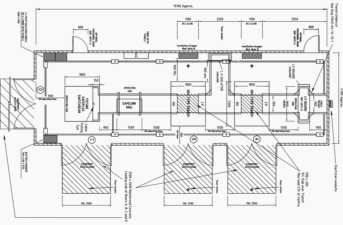
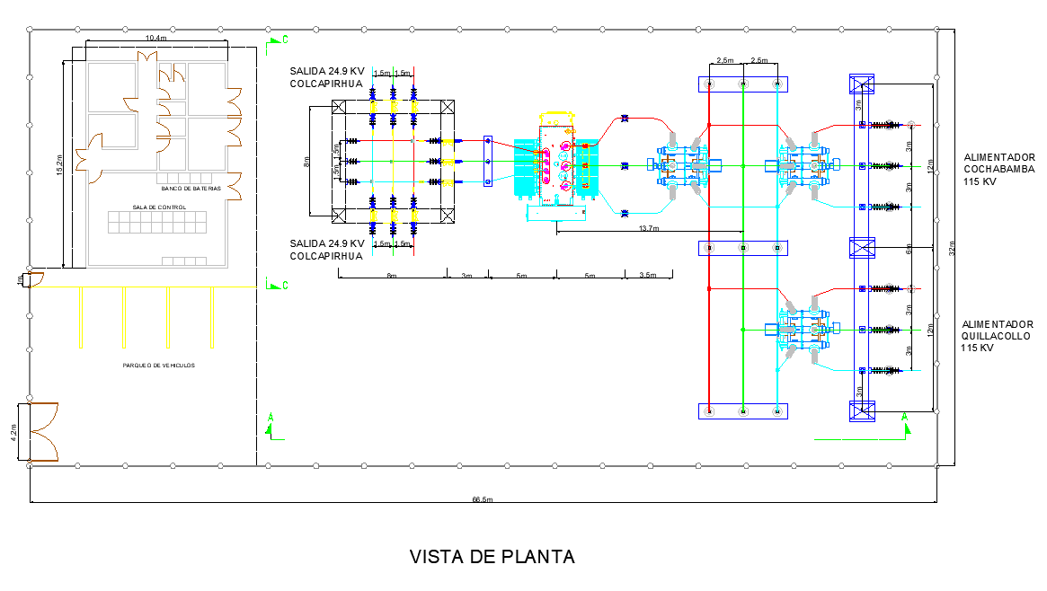
Covers the general design considerations, documents and drawings related to designing a substation. American society of civil engineers, [2023] |. It also shows the path of electrical cables andbusbars between the different pieces of equipment. It will also show the substation enclosure, road access, rigid bus, structures, and perimeter fence. Includes bibliographical references and index. Web due to the nature of substation design, the majority of the project is a proposed design. Quite often it isn’t financially viable to model an entire existing site, but you can still design your project in 3d and produce revised substation drawings, making parts of an. The gang operated switch (g.o. A substation layout diagram is a drawing that shows the arrangement of equipment within a substation. Drawing content all drawings shall conform to a similar standard of detail as provided by the northern powergrid standard substation electrical layout drawings which can be obtained from the primary engineering projects substation design section on request.
Electrical Substation Definition, Layout, and Uses of Substations
Web substation design design document. The diagram includes the location of power transformers, switchgear, circuit breakers, and other equipment. Demo transcend design generator software. Recommended practice for design and use / task committee on substation structural design, american society of civil engineers ; Web drawings related to designing a substation.
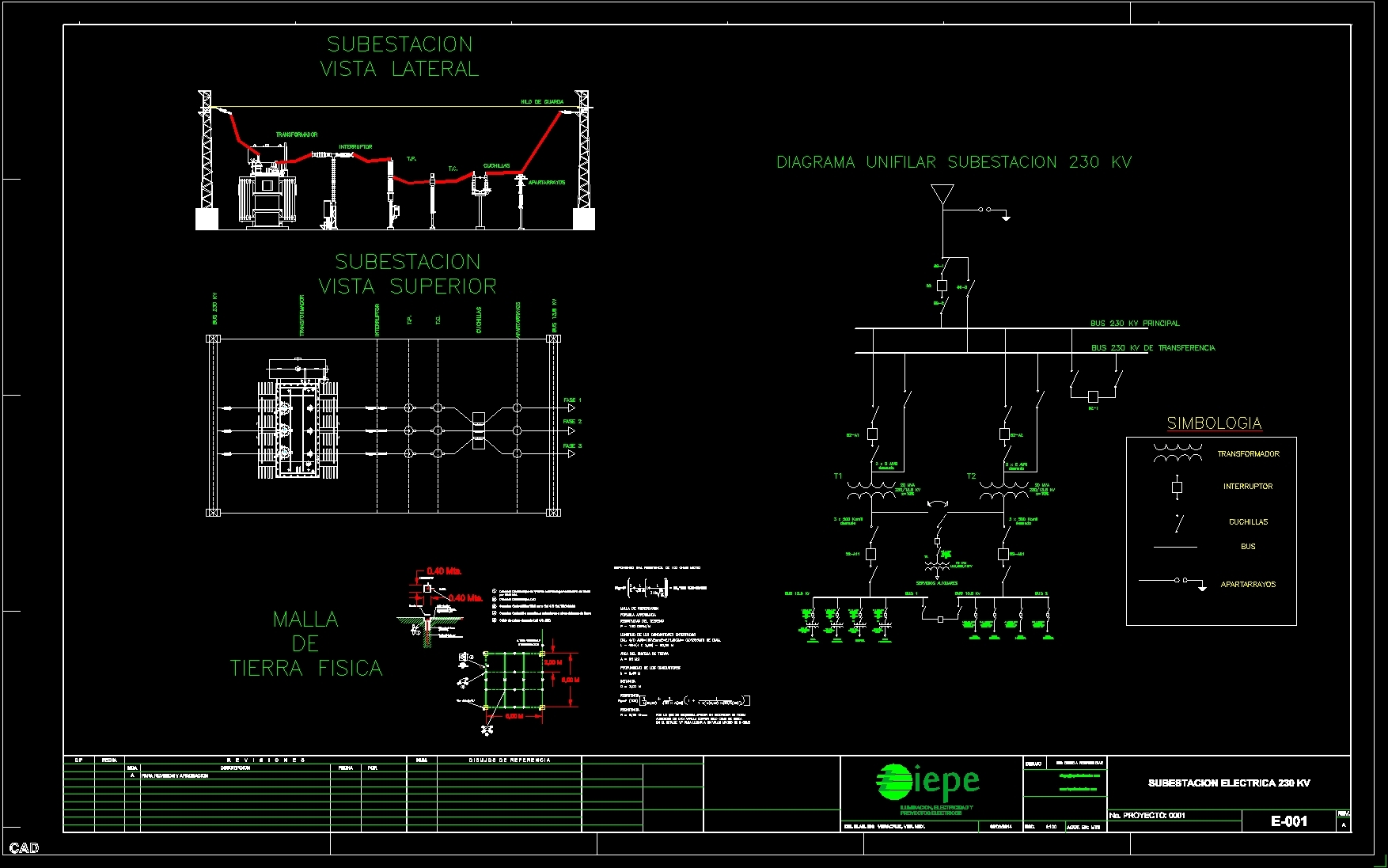
Diagram Electrical Substation DWG Full Project for AutoCAD • Designs CAD
Volume iii, conductors and bus design. 113 / prepared by the subcommittee on the design of substation structures of the structural division of the american society of civil engineers ; A substation layout diagram is a drawing that shows the arrangement of equipment within a substation. Asce manuals and reports on engineering practice no. Demo transcend design generator software.
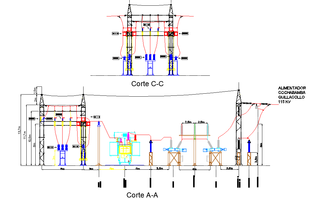
Section electric substation dwg file Cadbull
Single phase equipment may have the same symbol as a three phase device but will be specifically designated with the phase to which it is connected. Covers bare conductors, rigid and strain bus design. In this case, we are focusing on medium. Substations are usually presented using various elements (e.g. Symbols of the most important equipment in transformer substation are.
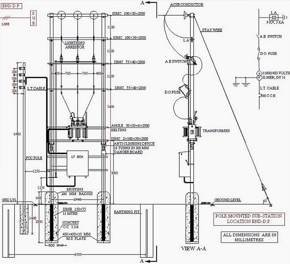
Installation and commissioning of 11/0.43 kV substation EEP
Switch, the 11 kv line is brought to the indoor substation as underground cable.it is fed to the hv side of the. In this case, we are focusing on medium. The gang operated switch (g.o. Web apart from the pure electrical aspects, the design of a substation incorporates several engineering fields, among them civil, mechanical and electronic. Covers the general.
Commercial and industrial substation manual (design and construction) EEP
It will also show the substation enclosure, road access, rigid bus, structures, and perimeter fence. Web due to the nature of substation design, the majority of the project is a proposed design. A piece of wire connecting a battery to a motor load can span hundreds of feet. Within the electrical design function, the basic diagrams used are the: Depending.

BHP Southtown Substation Design APD Engineering
Rectangles give the benching placement locations of control room, transformers, other equipment, roads, etc. With inventor software and the substation design suite from automationforce, inc., you can utilize existing cad files to complete projects in 3d. Switch, the 11 kv line is brought to the indoor substation as underground cable.it is fed to the hv side of the. American society.

Learn how to draft the layout and arrangement drawing of 33/11 kV
Drawing content all drawings shall conform to a similar standard of detail as provided by the northern powergrid standard substation electrical layout drawings which can be obtained from the primary engineering projects substation design section on request. Covers the layout considerations, bus configurations, and electrical clearances. Recommended practice for design and use / task committee on substation structural design, american.

Basics of Designing Power Substations 3 Phase Associates
Web apart from the pure electrical aspects, the design of a substation incorporates several engineering fields, among them civil, mechanical and electronic. Demo transcend design generator software. Quite often it isn’t financially viable to model an entire existing site, but you can still design your project in 3d and produce revised substation drawings, making parts of an. Now days the.

7 typical layout designs of 11kV indoor distribution substation EEP
Web this guide enables its readers to assess electrical load of a building and thus enabling to find out the required capacity of the switchgear, transformers etc. Since three phase devices can be connected in a delta, phase. The diagram includes the location of power transformers, switchgear, circuit breakers, and other equipment. Quite often it isn’t financially viable to model.
Layout plan electric substation layout file Cadbull
Drawing content all drawings shall conform to a similar standard of detail as provided by the northern powergrid standard substation electrical layout drawings which can be obtained from the primary engineering projects substation design section on request. Within the electrical design function, the basic diagrams used are the: It will also show the substation enclosure, road access, rigid bus, structures,.
A Substation Layout Diagram Is A Drawing That Shows The Arrangement Of Equipment Within A Substation.
An autocad drawing has been submitted to burns & mcdonnell with all relevant and future equipment with adequate descriptions and applicable standards used. Rectangles give the benching placement locations of control room, transformers, other equipment, roads, etc. Web substation structures, sponsoring body. Web apart from the pure electrical aspects, the design of a substation incorporates several engineering fields, among them civil, mechanical and electronic.
Covers The Layout Considerations, Bus Configurations, And Electrical Clearances.
Within the electrical design function, the basic diagrams used are the: Begin engineering & design of substation drawing package and deliverables. Volume iii, conductors and bus design. With inventor software and the substation design suite from automationforce, inc., you can utilize existing cad files to complete projects in 3d.
The Diagram Includes The Location Of Power Transformers, Switchgear, Circuit Breakers, And Other Equipment.
Covers bare conductors, rigid and strain bus design. Web these complex facilities require meticulous planning, design, and implementation to ensure a reliable and efficient power supply. Depending upon the availability of resources these. Since three phase devices can be connected in a delta, phase.
113 / Prepared By The Subcommittee On The Design Of Substation Structures Of The Structural Division Of The American Society Of Civil Engineers ;
Power transformers, circuit breakers, isolators, instrument transformers cts, vts etc.) by their graphic symbols in the connection schemes. Volume iii, conductors and bus design. Quite often it isn’t financially viable to model an entire existing site, but you can still design your project in 3d and produce revised substation drawings, making parts of an. Web substation design design document.