Symbols In Mechanical Drawing
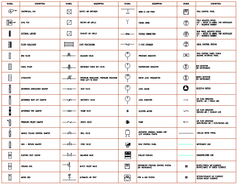
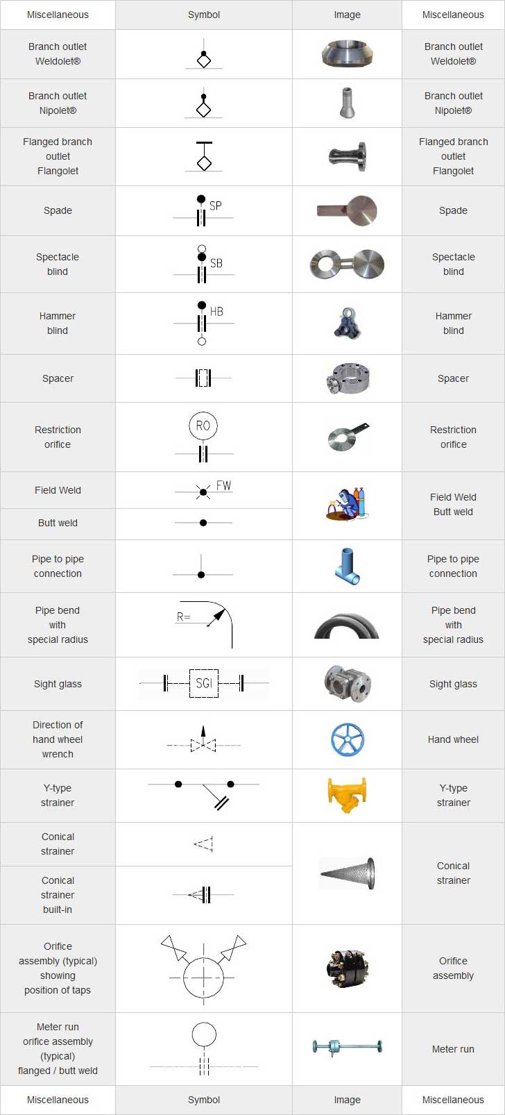
Symbols In Mechanical Drawing - Because there is no large space on a drawing to contain all the text to illustrate the image, abbreviations, and symbols are often used in engineering drawings to communicate the characteristics of the product to be. Common abbreviations include ac (alternating current), dc (direct current), fab (fabrication), and ld (load). Web hvac plan symbols. Web graphical symbols for use on mechanical engineering and construction drawings, diagrams, plans, maps and in relevant technical product documentation. The groove weld symbol indicates a weld made in a groove or channel. An introduction to the different types of blueprint tolerances you will encounter with plenty of examples to make them easy to understand. Each mechanical engineering office uses their own set of hvac symbols; Protestor don hindman was supportive of the 2020 school board’s decision to change the names of ashby lee elementary school and stonewall jackson. Web the table shows dimensioning symbols found on engineering and mechanical drawings. Gd&t is used to define the nominal (theoretically.
The title block appears either at the top or bottom of an engineering drawing. Each mechanical engineering office uses their own set of hvac symbols; Classification and symbols of geometric tolerance characteristics. They are also used to show the fillets given to strengthen the edges at connecting faces. Radius can be for the inside and outside curved surface on the part. These are just a few examples of the most commonly used engineering drawing symbols and their meanings. Web the basic drawing standards and conventions are the same regardless of what design tool you use to make the drawings. Two methods of dimensioning are in common use. Common abbreviations include ac (alternating current), dc (direct current), fab (fabrication), and ld (load). The groove weld symbol indicates a weld made in a groove or channel.
The groove weld symbol indicates a weld made in a groove or channel. Common abbreviations include ac (alternating current), dc (direct current), fab (fabrication), and ld (load). The following tables show how to construct the symbols. Two methods of dimensioning are in common use. Web these abbreviations can be found on engineering drawings such as mechanical, electrical, piping and plumbing, civil, and structural drawings. Symbols or conventions used on the drawing and any additional information the designeror draftsmanfeltwas necessaryto understandthedrawing. Each mechanical engineering office uses their own set of hvac symbols; 4 pdh a.bhatia continuing education and development, inc. Aerospace series — graphic symbols for schematic drawings of hydraulic and pneumatic systems and components. Users reported that in inventor drawing, moving text notes with symbol annotation (like sketch symbols or surface symbols) is inconsistent.
Engineering Drawing Symbols And Their Meanings Pdf at PaintingValley
Protestor don hindman was supportive of the 2020 school board’s decision to change the names of ashby lee elementary school and stonewall jackson. A radius dimension is preceded by an `r´. Read this first to find out crucial information about the drawing, including: Ala hijazi engineering working drawings basics page 10 of 22. Mechanical design is an important step in.
Mechanical Engineering Drawing Symbols Pdf Free Download at
Web inclusive names matter,” the protestors said. Symbols or conventions used on the drawing and any additional information the designeror draftsmanfeltwas necessaryto understandthedrawing. Web engineering drawing abbreviations and symbols are used to communicate and detail the characteristics of an engineering. Web the table shows dimensioning symbols found on engineering and mechanical drawings. Most symbols have been in y14.5 since at.
Machining Drafting Symbols
After selecting many elements at once, all drawing annotations will move together. Web smartdraw provides thousands of mechanical drawing symbols that you can drag and drop, then add lines and text. Because there is no large space on a drawing to contain all the text to illustrate the image, abbreviations, and symbols are often used in engineering drawings to communicate.
Mechanical Drawing Symbols Process Flow Diagram Symbols Electrical
As an integral part of cad/cam technology, cnc design is used to develop and produce. Web common mechanical drawing symbols. Refer to the symbol legend sheet for special symbols used in a particular set. Web the basic drawing standards and conventions are the same regardless of what design tool you use to make the drawings. The groove weld symbol indicates.
Mechanical Engineering Symbols Cadbull
Smartdraw works in both us/imperial and metric standards of measure and also allows you to customize the scale of your mechanical drawing. Arcs are also dimensioned on drawing with a radius. After selecting many elements at once, all drawing annotations will move together. Ala hijazi engineering working drawings basics page 10 of 22. Web gd&t drawings and symbols.
Mechanical Engineering Drawing Symbols Pdf Free Download at
Any needed height h 2 h h 2 h 60° 2 h identification letter datum feature symbol datum target symbol target point and. Two methods of dimensioning are in common use. Dimensioning and tolerancing with 45 elements; Gd&t is used to define the nominal (theoretically. Check the title block for basic information about the drawing.
M&e Drawing Symbols Back To Basics Komseq
If the drawing is made without either instruments or cad, it is called a freehand sketch. Aligned, the dimensions are written parallel to their dimension line. Any needed height h 2 h h 2 h 60° 2 h identification letter datum feature symbol datum target symbol target point and. They are also used to show the fillets given to strengthen.
Mechanical Engineering Drawing Symbols Pdf Free Download at
The title block appears either at the top or bottom of an engineering drawing. Classification and symbols of geometric tolerance characteristics. Gd&t is used to define the nominal (theoretically. Web geometric dimensioning and tolerancing symbols you can either create your own library of gd&t symbols, or use one of autocad’s gd&t fonts to insert the symbols as text. You can.
Engineering Drawing Symbols And Their Meanings Pdf at PaintingValley
However, the symbols below are fairly common across most mechanical drawings. Web geometric dimensioning and tolerancing symbols you can either create your own library of gd&t symbols, or use one of autocad’s gd&t fonts to insert the symbols as text. Web ask the assistant. Web smartdraw provides thousands of mechanical drawing symbols that you can drag and drop, then add.
Technical Drawing Symbols And Their Meanings Design Talk
Symbols or conventions used on the drawing and any additional information the designeror draftsmanfeltwas necessaryto understandthedrawing. Toleranced characteristics and symbols — examples of indication and interpretation. In learning drafting, we will approach it from the perspective of manual drafting. Web a good design drawing can indicate all the details needed to produce a mechanical cnc milling part in an easy.
Geometric Tolerances Are Specified Using Symbols On A Drawing.
Read this first to find out crucial information about the drawing, including: Aerospace series — graphic symbols for schematic drawings of hydraulic and pneumatic systems and components. Web hvac plan symbols. Web smartdraw provides thousands of mechanical drawing symbols that you can drag and drop, then add lines and text.
Dimensioning And Tolerancing With 45 Elements;
Here are some common engineering drawing abbreviations used in technical drawings: Web the basic drawing standards and conventions are the same regardless of what design tool you use to make the drawings. You can even flip between scales on the fly. Refer to the symbol legend sheet for special symbols used in a particular set.
The Spot Weld Symbol Represents A Circular Weld Made By Applying Pressure And Heat.
In learning drafting, we will approach it from the perspective of manual drafting. The following tables show how to construct the symbols. After selecting many elements at once, all drawing annotations will move together. Two methods of dimensioning are in common use.
As An Integral Part Of Cad/Cam Technology, Cnc Design Is Used To Develop And Produce.
Web engineering drawing abbreviations and symbols are used to communicate and detail the characteristics of an engineering. Currently, we have 16 symbols for geometric tolerances, which are categorized according to the tolerance they specify. True position theory (size value in rectangular frame) However, the symbols below are fairly common across most mechanical drawings.


