Symbols On Drawings
Symbols On Drawings - It is the size that the tolerance envelope is based on. Web list of drafting symbols. Web may 5, 2022 by brandon fowler. This list includes abbreviations common to the vocabulary of people who work with engineering drawings in the manufacture and inspection of parts and assemblies. The symbols represent electrical and electronic components. Mep (mechanical, electrical, and plumbing) a. Classification and symbols of geometric tolerance characteristics; Below, you’ll find our list of drafting symbols in alphabetical order. Web gd&t symbol charts for engineering drawing & drafting. The following is a short list of symbols that normally appear on a technical drawing and need understanding.
They are 1) piping and instrument drawings (p&ids), 2) electrical single lines and schematics, 3) electronic diagrams and schematics, 4) logic diagrams and prints, and 5) fabrication, construction, and architectural drawings. Below, you’ll find our list of drafting symbols in alphabetical order. Unlike a model, engineering drawings offer more specific detail and requirements, such as: Web this chapter will introduce the five common categories of drawings. Mep (mechanical, electrical, and plumbing) a. These symbols provide essential information about the materials, processes and installations involved to turn the plans into reality. They are not very complicated items but shockingly i have some. It is more than simply a drawing, it is a graphical language that communicates ideas and information. Web the following are definitions commonly used throughout industry when discussing gd&t or composing engineering drawing notes. Web common symbols in construction drawings and what they mean.
Here are more commonly used engineering drawing symbols and design elements as below. Web electrical symbols and electronic circuit symbols are used for drawing schematic diagram. Web welding symbols are the integral part and the basic requirements for fabrication as they provide vital information for the welding joint location, weld size (throat or leg length, depth of penetration) & length, weld type & quality requirements for the fabrication or construction drawing. How a particular piece of art is interpreted will depend primarily on the viewer and their background. Web this chapter will introduce the five common categories of drawings. Web gd&t symbol charts for engineering drawing & drafting. True position theory (size value in rectangular frame) Gd&t flatness is a common symbol that references how flat a surface is regardless of any other datum’s or features. They are 1) piping and instrument drawings (p&ids), 2) electrical single lines and schematics, 3) electronic diagrams and schematics, 4) logic diagrams and prints, and 5) fabrication, construction, and architectural drawings. Currently, we have 16 symbols for geometric tolerances, which are categorized according to the tolerance they specify.

Mechanical Engineering Drawing Symbols Pdf Free Download at
Why not just use a 3d model? Web gd&t drawings and symbols. This document describes and illustrates common dimensioning, gd&t, architectural, piping, and electrical symbols. It is the size that the tolerance envelope is based on. Welding symbol chart (desk size)

Standard Architectural Drawing Symbols
The following is a short list of symbols that normally appear on a technical drawing and need understanding. These standardized symbols are understood by all trades and other individuals involved with the project. Currently, we have 16 symbols for geometric tolerances, which are categorized according to the tolerance they specify. Time for the next installment of architectural graphics 101, and.

Engineering Drawing Symbols And Their Meanings Pdf at PaintingValley
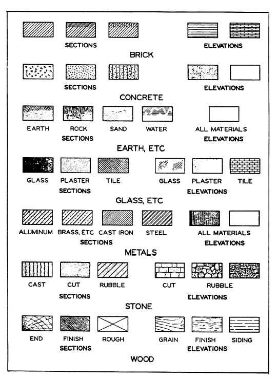
Classification and symbols of geometric tolerance characteristics; Web common symbols in construction drawings and what they mean. Construction drawings use a variety of symbols to represent different elements and systems within a building. There are literally hundreds of engineering drawing symbols and they’re used in a variety of ways. How a particular piece of art is interpreted will depend primarily.

ANSI Standard JSTD710 Architectural Drawing Symbols Bedrock Learning
Web may 5, 2022 by brandon fowler. Web common symbols in construction drawings and what they mean. The symbols represent electrical and electronic components. Web gd&t drawings and symbols. You can also check out the gd&t symbols and terms on our site.

Civil Engineering Drawing Symbols And Their Meanings at PaintingValley
How a particular piece of art is interpreted will depend primarily on the viewer and their background. Web standard symbols for drawings. There are many other commonly used symbols and we’ll explore those in this article. The table shows dimensioning symbols found on engineering and mechanical drawings. This list includes abbreviations common to the vocabulary of people who work with.

How To Read Architectural Drawings Symbols The Architect
The table shows dimensioning symbols found on engineering and mechanical drawings. Classification and symbols of geometric tolerance characteristics; These standardized symbols are understood by all trades and other individuals involved with the project. True position theory (size value in rectangular frame) These symbols provide essential information about the materials, processes and installations involved to turn the plans into reality.

Engineering Drawing Symbols And Their Meanings Pdf at PaintingValley
Welding symbol chart (desk size) May 24, 2021 by bob borson 27 comments. The table shows dimensioning symbols found on engineering and mechanical drawings. Web drafting symbols symbols provide a “common language” for drafters all over the world. Web engineering drawing abbreviations and symbols are used to communicate and detail the characteristics of an engineering drawing.

Technical Drawing Symbols
The symbols represent electrical and electronic components. Many of the definitions are not official asme, ansi or iso terminology. Web how to read an engineering drawing symbol. This document describes and illustrates common dimensioning, gd&t, architectural, piping, and electrical symbols. This list includes abbreviations common to the vocabulary of people who work with engineering drawings in the manufacture and inspection.
Engineering Drawing Symbols And Their Meanings Pdf at PaintingValley
Web different types of symbols in construction drawings. Web engineering drawings (aka blueprints, prints, drawings, mechanical drawings) are a rich and specific outline that shows all the information and requirements needed to manufacture an item or product. Web various symbols and abbreviations in engineering drawings give you information about the dimensions, design, and materials used. Web engineering drawing abbreviations and.

M&e Drawing Symbols Back To Basics Komseq
The following is a short list of symbols that normally appear on a technical drawing and need understanding. Web various symbols and abbreviations in engineering drawings give you information about the dimensions, design, and materials used. These symbols provide essential information about the materials, processes and installations involved to turn the plans into reality. It is the size that the.
There Are Literally Hundreds Of Engineering Drawing Symbols And They’re Used In A Variety Of Ways.
Web this chapter will introduce the five common categories of drawings. This is the place to learn about engineering symbology, different types of drawings and documents, and how to use modern technology to simplify collaboration. In the industry of design and architecture, standardized symbols are used to represent various elements found in drawings. Many of the definitions are not official asme, ansi or iso terminology.
Note The Comparison With The Iso Standards.
Web welding symbols are the integral part and the basic requirements for fabrication as they provide vital information for the welding joint location, weld size (throat or leg length, depth of penetration) & length, weld type & quality requirements for the fabrication or construction drawing. Web various symbols and abbreviations in engineering drawings give you information about the dimensions, design, and materials used. The table shows dimensioning symbols found on engineering and mechanical drawings. It is more than simply a drawing, it is a graphical language that communicates ideas and information.
It Comes In Useful If A Feature Is To Be Defined On A Drawing That Needs To Be Uniformly Flat Without.
May 24, 2021 by bob borson 27 comments. Web gd&t symbol charts for engineering drawing & drafting. How a particular piece of art is interpreted will depend primarily on the viewer and their background. Web may 5, 2022 by brandon fowler.
This List Includes Abbreviations Common To The Vocabulary Of People Who Work With Engineering Drawings In The Manufacture And Inspection Of Parts And Assemblies.
Time for the next installment of architectural graphics 101, and this time i decided to take a look at architectural symbols which are really wayfinding devices for our construction drawings. Web the following are definitions commonly used throughout industry when discussing gd&t or composing engineering drawing notes. Web common symbols in construction drawings and what they mean. Or a rose to symbolize romance or love.