The Drawing Shows A Uniform Horizontal Beam
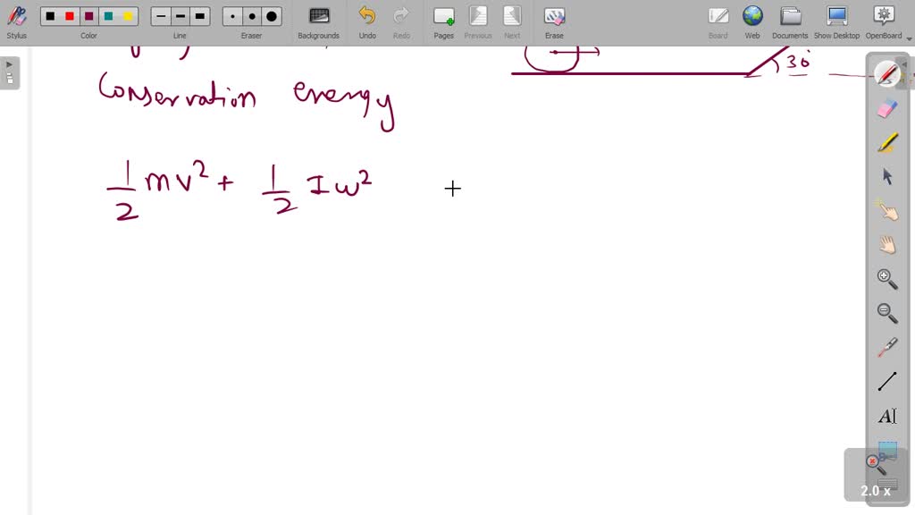
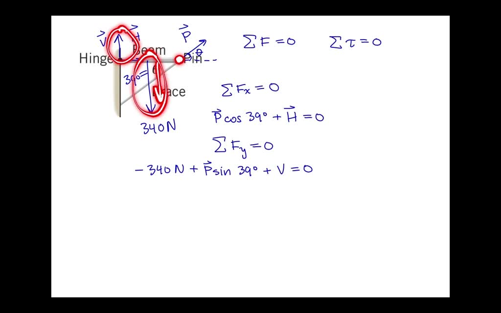
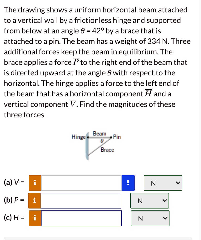
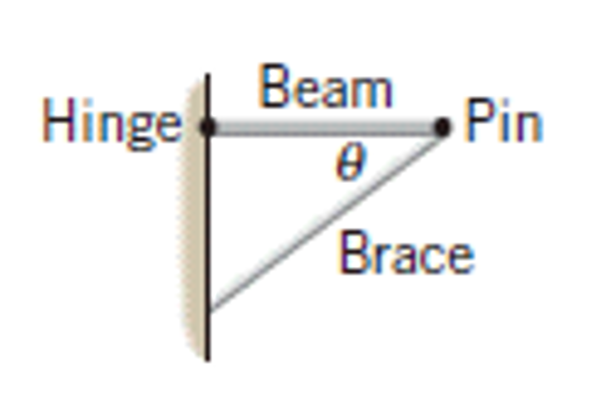
The Drawing Shows A Uniform Horizontal Beam - Web the drawing shows a uniform horizontal beam attached to a vertical wall by a frictionless hinge and supported from below at an angle θ = 37° by a brace that is attached to a pin. Web to determine it for a given height \(y\) relative to the neutral axis, begin by sketching the beam cross section, and draw a horizontal line line at the position \(y\) at which \(q\) is sought (figure 10 shows a rectangular beam of of. The beam is stationary and in equilibrium. The failure modes of the joint region and the overall steel frame structure under the action of the earthquake need to be studied. The drawing shows a uniform horizontal beam attached to a vertical wall by a frictionless hinge and supported from below at an angle \theta=39^ {\circ} θ = 39∘ by a brace that is attached to a pin. Both weights act vertically on the beam as shown in the diagram. We can start by considering the horizontal forces. The beam is in equilibrium, which means the sum of the forces and the sum of the torques (moments) acting on it must be zero. Web the drawing shows a uniform horizontal beam attached to a vertical wall by a frictionless hinge and supported from below at an angle θ = 39 ∘ by a brace that is attached to a pin. The beam has a weight of 340 n.
The beam has a weight of 340 n. Web the drawing shows a uniform horizontal beam attached to a vertical wall by a frictionless hinge and supported from below at an angle θ = 44 o by a brace that is attached to a pin. The drawing shows a uniform horizontal beam attached to a vertical wall by a frictionless hinge and supported from below at an angle \theta=39^ {\circ} θ = 39∘ by a brace that is attached to a pin. The drawing shows a uniform horizontal beam attached to a vertical wall by a frictionless hinge and supported from below at an angle θ = 390 by a brace attached to a pin. The drawing shows a uniform horizontal beam attached to a vertical wall by a frictionless hing and supported from below at an angle. The beam has a weight of 348 n. The beam is in equilibrium, which means the sum of the forces and the sum of the torques (moments) acting on it must be zero. First, we need to consider the forces acting on the beam. Web the drawing shows a uniform horizontal beam attached to a vertical wall by a frictionless hinge and supported from below at an angle = 39° by a brace that is attached to a pin. Three additional forces keep the beam in equilibrium.
Three additional forces keep the beam in equilibrium. Web the drawing shows a uniform horizontal beam attached to a vertical wall by a frictionless hinge and supported from below at an angle = 39° by a brace that is attached to a pin. Web the diagram shows a uniform horizontal beam of negligible mass, 5.0 m long, placed on two supports, one at each end. Three additional forces keep the beam in equilibrium. The drawing shows a uniform horizontal beam attached to a vertical wall by a frictionless hinge and supported from below at an angle θ=39∘ by a brace attached to a pin. The drawing shows a uniform horizontal beam attached to a vertical wall by a frictionless hinge and supported from below at an angle = 39° by a brace that is attached to a pin. The beam has a weight of 342 n. Web the drawing shows a uniform horizontal beam attached to a vertical wall by a frictionless hinge and supported from below at an angle theta = 44 degrees by a brace that is attached to a. The beam has a weight of 340 n. The beam has a weight of 34 n.
Solved The drawing shows a uniform horizontal beam attached
Both weights act vertically on the beam as shown in the diagram. The beam weighs 340 n. Three additional forces keep the beam in equilibrium. Web the drawing shows a uniform horizontal beam attached to a vertical wall by a frictionless hing and supported from below at an angle $\theta=39^{\circ}$ by a brac that is attached to a pin. Web.
Solved = The drawing shows a uniform horizontal beam
Web a uniform horizontal beam attached to a vertical wall by a frictionless hinge and supported from below a tan angle 39 by a brace that is attached to a pin. Web to determine it for a given height \(y\) relative to the neutral axis, begin by sketching the beam cross section, and draw a horizontal line line at the.
Solved The drawing shows a uniform horizontal beam attached
No views 1 minute ago. The beam is in equilibrium, which means the sum of the forces and the sum of the torques (moments) acting on it must be zero. Three additional forces keep the beam in equilibrium. Web the drawing shows a uniform horizontal beam attached to a vertical wall by a frictionless hinge and supported from below at.
Solved The drawing shows a uniform horizontal beam attached
Three additional forces keep the beam in equilibrium. The drawing shows a uniform horizontal beam attached to a vertical wall by a frictionless hinge and supported from below at an angle \theta=39^ {\circ} θ = 39∘ by a brace that is attached to a pin. Three additional forces keep the beam in equilibrium. Three additional forces keep the beam in.
SOLVEDPart a of the drawing shows a uniform horizontal beam attached
Web the drawing shows a uniform horizontal beam attached to a vertical wall by a frictionless hinge and supported from below at an angle θ = 39 ∘ by a brace that is attached to a pin. Web the drawing shows a uniform horizontal beam attached to a vertical wall by a frictionless hinge and supported from below at an.
SOLVEDThe drawing shows a uniform horizontal beam attached to a
Web the drawing shows a uniform horizontal beam attached to a vertical wall by a frictionless hinge and supported from below at an angle θ = 39 ∘ by a brace that is attached to a pin. Web the drawing shows a uniform horizontal beam attached to a vertical wall by a frictionless hinge and supported from below at an.
[Solved] The drawing shows a uniform horizontal beam attached to a
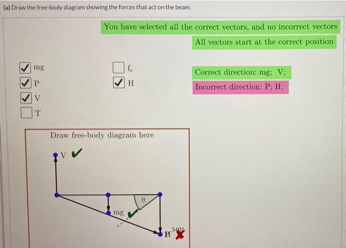
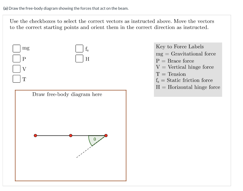
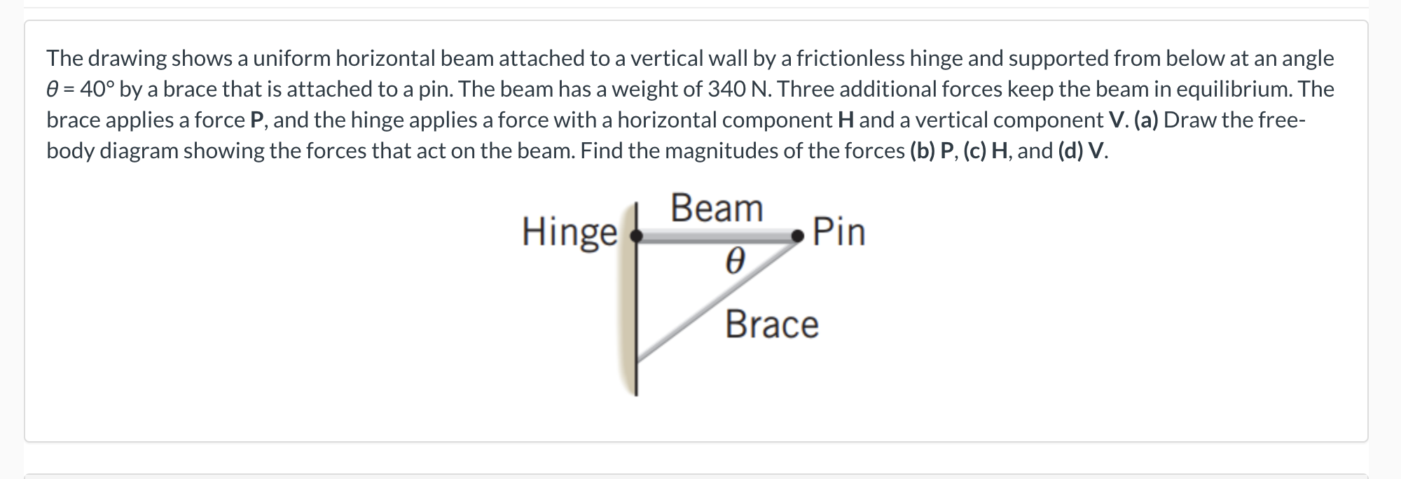
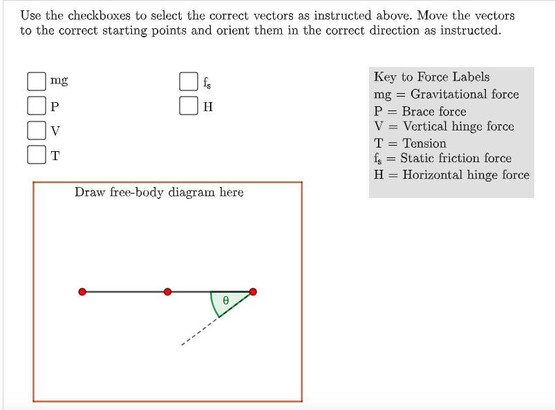
Three additional forces keep the beam in equilibrium. Web the drawing shows a uniform horizontal beam attached to a vertical wall by a frictionless hinge and supported from below at an angle θ = 40° by a brace that is attached to a pin. Web the diagram shows a uniform beam supported by two light cables, ab and ac, which.
SOLVED The drawing shows a uniform horizontal beam attached to a
Web the drawing shows a uniform horizontal beam attached to a vertical wall by a frictionless hinge and supported from below at an angle θ = 4 1 ∘ by a brace that is attached to a pin. The beam has a weight of 340 n. Web to determine it for a given height \(y\) relative to the neutral axis,.
Solved The drawing shows a uniform horizontal beam attached
Web the diagram shows a uniform beam supported by two light cables, ab and ac, which are. Three additional forces keep the beam in equilibrium. Web the drawing shows a uniform horizontal beam attached to a vertical wall by a frictionless hinge and supported from below at an angle theta = 44 degrees by a brace that is attached to.
Solved The drawing shows a uniform horizontal beam attached
Three additional forces keep the beam in equilibrium. The drawing shows a uniform horizontal beam attached to a vertical wall by a frictionless hinge and supported from below at an angle θ = 390 by a brace attached to a pin. Both weights act vertically on the beam as shown in the diagram. It has a 300 n weight placed.
The Drawing Shows A Uniform Horizontal Beam Attached To A Vertical Wall By A Frictionless Hinge And Supported From Below At An Angle Θ = 390 By A Brace Attached To A Pin.
Web the drawing shows a uniform horizontal beam attached to a vertical wall by a frictionless hinge and supported from below at an angle θ = 37° by a brace that is attached to a pin. Web the drawing shows a uniform horizontal beam attached to a vertical wall by a frictionless hinge and supported from below at an angle θ =39∘ θ = 39 ∘ by a brace that is attached to a pin. Three additional forces keep the beam in equilibrium. The drawing shows a uniform horizontal beam attached to a vertical wall by a frictionless hinge and supported from below at an angle \theta=39^ {\circ} θ = 39∘ by a brace that is attached to a pin.
Web The Drawing Shows A Uniform Horizontal Beam Attached To A Vertical Wall By A Frictionless Hinge And Supported From Below At An Angle Θ = 40° By A Brace That Is Attached To A Pin.
Three additional forces keep the beam in equilibrium. Web a uniform horizontal beam attached to a vertical wall by a frictionless hinge and supported from below a tan angle 39 by a brace that is attached to a pin. First, we need to consider the forces acting on the beam. The beam has a weight of 340 n.
Web The Drawing Shows A Uniform Horizontal Beam Attached To A Vertical Wall By A Frictionless Hinge And Supported From Below At An Angle Θ = 39 ∘ By A Brace That Is Attached To A Pin.
Three additional forces keep the beam in equilibrium. Three additional forces keep the beam in equilibrium. No views 1 minute ago. = 39° by a brace that is attached to a pin.
The Drawing Shows A Uniform Horizontal Beam Attached To A Vertical Wall By A Frictionless Hinge And Supported From Below At An Angle = 39° By A Brace That Is Attached To A Pin.
The seismic performance of different types of weakened. What are the upward forces from the two supports. We can start by considering the horizontal forces. Both weights act vertically on the beam as shown in the diagram.