Valve Symbols On Drawings
Valve Symbols On Drawings - Rotate a disc or ellipse about a shaft extending across the diameter of an orifice (for example, a butterfly or ball valve). The symbology for the identification of the measurement and control instrumentation on the flow and process diagrams and on the p&id (piping & instrument diagram), commonly called p&i (piping & instrumentation), is generally compliant with the standard isa (instrumentation society of automation) identified as. Users reported that in inventor drawing, moving text notes with symbol annotation (like sketch symbols or surface symbols) is inconsistent. The ball valve symbol has a larger circle indicating the ball. Process lines depict the conduits for the. Web the ultimate guide to understanding valve symbols. Web a p&id is a detailed, visual representation of a process system. The direction of flow is shown by the arrowhead on the line symbols. Web line symbols for pfd and p&id. You can see that p&id and isometric.
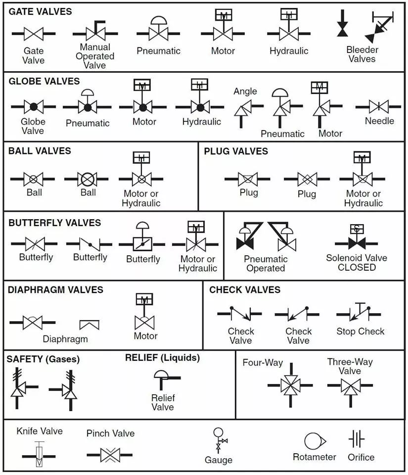
Web the piping and instrumentation diagram for the diaphragm valves is obtained by drawing a bow tie and a straight horizontal line through its center. Web valve symbols are used to signify the pressure, flow and direction of fluids through a valve. They embody the functionality, type, and operation of valves in piping and. For a globe valve, a symbol is modified by adding a small dark circle between triangles. These illustrations, commonly referred to as piping and instrumentation diagram (p&di) symbols, may vary slightly between organizations but similar sketches are used to identify types and position of valves. Valve symbols are the shorthand of engineering, a language that allows professionals across the globe to communicate complex ideas through simple, standardised representations. They typically have a wheel handle that gets turned to operate the metal disk that blocks the flow. Finish by erasing the top half. Piping and instrumentation diagrams, or p&ids, are used to create important documentation for process industry facilities. This type of valve symbol looks similar to the globe valve.
A p&id provides the design and construction sequence for the plants for systematic planning of. Rotate a disc or ellipse about a shaft extending across the diameter of an orifice (for example, a butterfly or ball valve). Web type of valve employed depends on nature of fluid, flow control required, operating pressure and temperatures as well as surround atmosphere. The p&id drawings help them to track the interconnection between the piping and instrumentation and equipment. Finish by erasing the top half. A gate valve will open or cut off the flow of water through a pipe. Web piping and instrumentation diagrams (p&ids) use specific symbols to show the connectivity of equipment, sensors, and valves in a control system. Valve symbols are the shorthand of engineering, a language that allows professionals across the globe to communicate complex ideas through simple, standardised representations. Web the piping and instrumentation diagram for the diaphragm valves is obtained by drawing a bow tie and a straight horizontal line through its center. Web the ultimate guide to understanding valve symbols.

Symbol of valves in piping valves symbols on drawings YouTube
A p&id provides the design and construction sequence for the plants for systematic planning of. The ball valve symbol has a larger circle indicating the ball. Besides valve symbols and their states, you will come across process lines in p&ids. A rotary valve turns only at 90°. Web move a disc, or plug into or against an orifice (for example,.

Valve Symbols in P&ID Ball Valve, Relief Valve and more
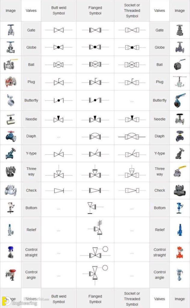
Web isometric drawing symbols for piping valves. Rotate a disc or ellipse about a shaft extending across the diameter of an orifice (for example, a butterfly or ball valve). This type of valve symbol looks similar to the globe valve. For a globe valve, a symbol is modified by adding a small dark circle between triangles. Web type of valve.

Types Of Valves, Their Functions And Symbols Engineering Discoveries
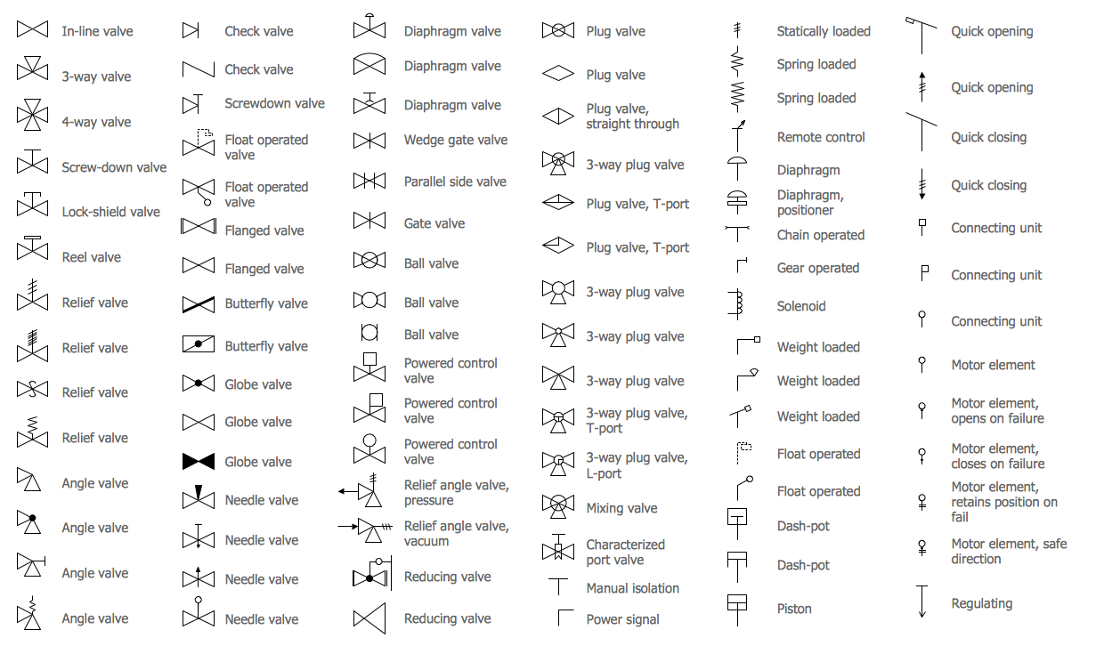
A valve is an element in a piping system that regulates the flow. Valve symbols are the shorthand of engineering, a language that allows professionals across the globe to communicate complex ideas through simple, standardised representations. Web valve symbols are used to signify the pressure, flow and direction of fluids through a valve. The symbols for these components aren’t drawn.
Valve Symbols for P&IDs The Engineering Concepts
Web as we draw the curtain on this comprehensive exploration of “valve symbols 101: Web engineering fluids diagrams and prints. Web the piping and instrumentation diagram for the diaphragm valves is obtained by drawing a bow tie and a straight horizontal line through its center. They embody the functionality, type, and operation of valves in piping and. These symbols can.

Valve Symbols 101 A Comprehensive Guide
Symboles for gate, globe, check, plug, ball valve, etc. Its symbol looks like the outline of a bowtie with two straight lines crossing each other to form an “x”. Process lines depict the conduits for the. Web a ball valve uses a hollow, rotating ball with a hole going through the ball. P&ids provide more detail than a process flow.
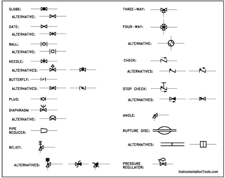
Piping and Instrumentation Symbols Instrumentation Tools
Web the control valve symbols on a p&id differ depending on the type of valve specified for the application. Symboles for gate, globe, check, plug, ball valve, etc. This type of valve symbol looks similar to the globe valve. Web move a disc, or plug into or against an orifice (for example, globe or needle type valve). Its symbol looks.
Valves Symbols Rooter Hero University
You can also see the symbols for pneumatic, hydraulic, and capillary lines. A p&id provides the design and construction sequence for the plants for systematic planning of. Web the piping and instrumentation diagram for the diaphragm valves is obtained by drawing a bow tie and a straight horizontal line through its center. The symbology for the identification of the measurement.

Valve Symbols Free CAD Block And AutoCAD Drawing
And the solid sides of the ball line up with the inlet/outlet when the valve is closed. They typically have a wheel handle that gets turned to operate the metal disk that blocks the flow. Rotate a disc or ellipse about a shaft extending across the diameter of an orifice (for example, a butterfly or ball valve). For a globe.

Valves Symbols used in P&ID and Piping Isometric drawings YouTube
Web isometric drawing symbols for piping valves. These symbols are not just drawings; A rotary valve turns only at 90°. These symbols can represent actuators, sensors, and controllers and may be apparent in most, if not all, system diagrams. The shapes in this legend are representative of the functional relationship between piping, instrumentation, and system equipment units.
Types Of Valves, Their Functions And Symbols Engineering Discoveries
Here is a list of symbols for various types of valves used in process industry. Web line symbols for pfd and p&id. Web types of valves with p&id symbols. To read and understand engineering fluid diagrams and prints, usually referred to as p&ids, an individual must be familiar with the basic symbols. Web valve symbols are used to signify the.
The Symbols For These Components Aren’t Drawn To Scale And Aren’t Intended To Be Dimensionally.
The ball valve symbol has a larger circle indicating the ball. The p&id is the primary schematic drawing used for laying out a process control system’s installation. You can also see the symbols for pneumatic, hydraulic, and capillary lines. The symbology for the identification of the measurement and control instrumentation on the flow and process diagrams and on the p&id (piping & instrument diagram), commonly called p&i (piping & instrumentation), is generally compliant with the standard isa (instrumentation society of automation) identified as.
Slide A Flat, Cylindrical, Or Spherical Surface Across An Orifice (For Example, Gate And Plug Valves).
P&ids provide more detail than a process flow diagram with the exception of. Web type of valve employed depends on nature of fluid, flow control required, operating pressure and temperatures as well as surround atmosphere. Eo 1.1 identify the symbols used on engineering p&ids for the following types of valves: We've broken them down into seven main groups:
Besides Valve Symbols And Their States, You Will Come Across Process Lines In P&Ids.
Rotate a disc or ellipse about a shaft extending across the diameter of an orifice (for example, a butterfly or ball valve). Piping and instrumentation diagrams, or p&ids, are used to create important documentation for process industry facilities. These illustrations, commonly referred to as piping and instrumentation diagram (p&di) symbols, may vary slightly between organizations but similar sketches are used to identify types and position of valves. The hole lines up with the inlet/outlet when it is open.
Main Process Lines Are Shown As Dark Black Lines, Whereas Minor Lines Are Shown As Thin Black Lines.
Web a p&id is a detailed, visual representation of a process system. Web three symbols shown below are the gate valve symbols used in isometric drawings. Web as we draw the curtain on this comprehensive exploration of “valve symbols 101: Web valve symbols are used to signify the pressure, flow and direction of fluids through a valve.