What Is Engineering Drawing
What Is Engineering Drawing - Web engineering drawing basics explained. Hence engineering drawing is a technical drawing conveying information. Web what is drawing in engineering? Web although engineers created the engineering drawings in the past by hand, today, they are primarily done in cad software like autodesk fusion 360. Web engineering drawing, most commonly referred to as engineering graphics, is the art of manipulation of designs of a variety of components, especially those related to engineering. Drawings for specialized engineering disciplines (e.g., marine, civil, construction, optics, etc.) are not included in this. Web engineering drawings are a collection of standardized language, symbols, and graphic patterns to convey all the information needed to manufacture a product or part. However, if the object in figure 2 had a hole on the back. Web engineering drawings are used to communicate design ideas and technical information to engineers and other professionals throughout the design process. If the isometric drawing can show all details and all dimensions on one drawing, it is ideal.
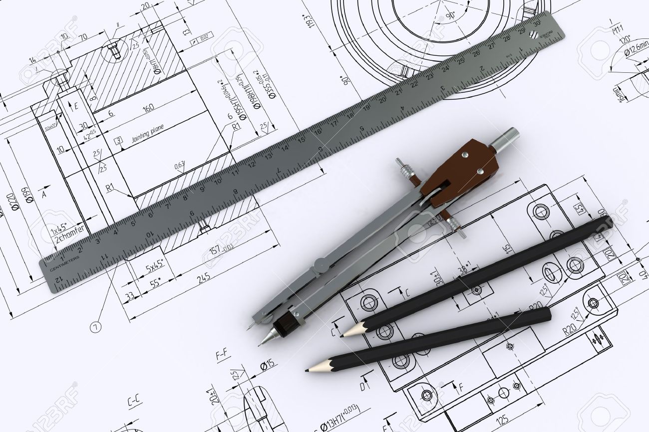
Protected endwalls for round & oval pipes (pipe sizes 18” to 72”, all skews, 2:1 & 3:1 slopes) for endwall dimension labeling The process of producing engineering drawings is often referred to as technical drawing or drafting (draughting). It provides all the necessary information about the object, such as its shape, size, material, and manufacturing process. Web engineering drawing basics explained. It is more than simply a drawing, it is a graphical language that communicates ideas and information. It helps to define the requirements of an engineering part. Engineering drawings use standardised language and symbols. If the isometric drawing can show all details and all dimensions on one drawing, it is ideal. The purpose is to convey all the information necessary for manufacturing a product or a part. Web although engineers created the engineering drawings in the past by hand, today, they are primarily done in cad software like autodesk fusion 360.
The purpose is to convey all the information necessary for manufacturing a product or a part. Web engineering drawings are a collection of standardized language, symbols, and graphic patterns to convey all the information needed to manufacture a product or part. It is the universal “engineering technology language” in the world. Usually, a number of drawings are necessary to completely specify even a simple component. What are the different types of drawing instruments and its uses ? Engineering drawing | definition, types and reasons for studying | errol karl gumagayat the end of this lesson, the learners shall be able to:a. It’s an essential skill that translates complex ideas and theoretical designs into visual blueprints. One can pack a great deal of information into an isometric drawing. Protected endwalls for round & oval pipes (pipe sizes 18” to 72”, all skews, 2:1 & 3:1 slopes) for endwall dimension labeling This standard defines the types of engineering drawings most frequently used to establish engineering requirements.
Engineering Drawing A Science or Art RRCE
Web engineering drawings (aka blueprints, prints, drawings, mechanical drawings) are a rich and specific outline that shows all the information and requirements needed to manufacture an item or product. Engineering drawings are also known as mechanical drawings, manufacturing blueprints and drawings. These drawings are essentially the blueprints or plans for manufacturing a wide array of products and structures. A complete.

Engineering Drawing And Graphics FerisGraphics
Engineering drawings are also known as mechanical drawings, manufacturing blueprints and drawings. These drawings are essentially the blueprints or plans for manufacturing a wide array of products and structures. It primarily consists of sketching the actual component, for example, a machine, with its exact dimensions, and using entities such as points, lines, arcs,. Web an engineering drawing is a type.

Engineering Drawing Symbols And Their Meanings Pdf at GetDrawings
Web what is engineering drawing? Web engineering drawing, most commonly referred to as engineering graphics, is the art of manipulation of designs of a variety of components, especially those related to engineering. It primarily consists of sketching the actual component, for example, a machine, with its exact dimensions, and using entities such as points, lines, arcs,. Web engineering drawing basics.
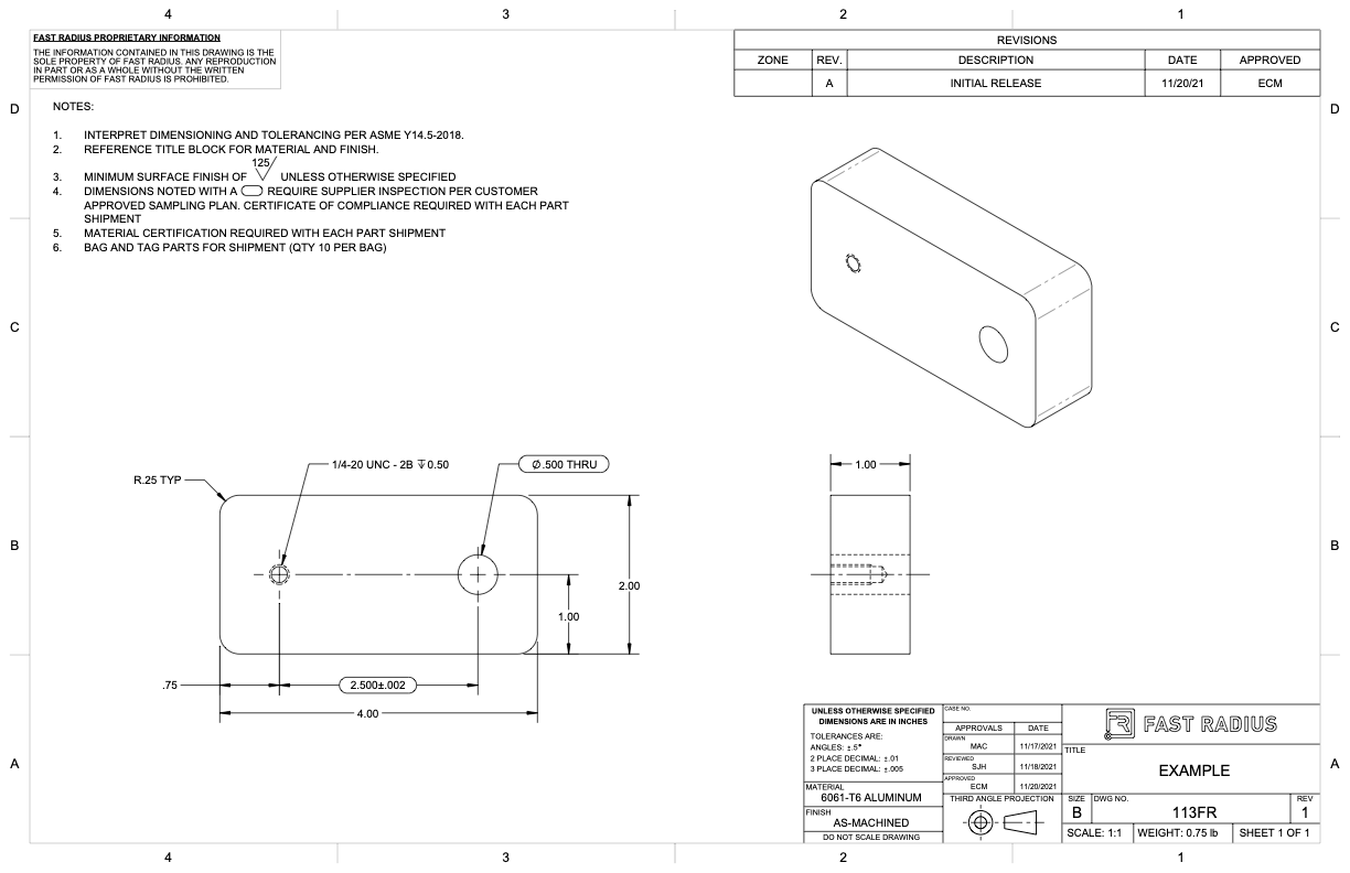
What to Include in Your Engineering Drawing Fast Radius
If the isometric drawing can show all details and all dimensions on one drawing, it is ideal. Import) a 3d model, and then we start inserting the views in the drawing and adding dimensions. One can pack a great deal of information into an isometric drawing. Engineering drawings, also known as mechanical drawings, manufacturing blueprints, drawings, etc., are technical drawings.
Engineering Drawing at GetDrawings Free download
It is the universal “engineering technology language” in the world. The purpose is to convey all the information necessary for manufacturing a product or a part. These drawings are essentially the blueprints or plans for manufacturing a wide array of products and structures. Web although engineers created the engineering drawings in the past by hand, today, they are primarily done.
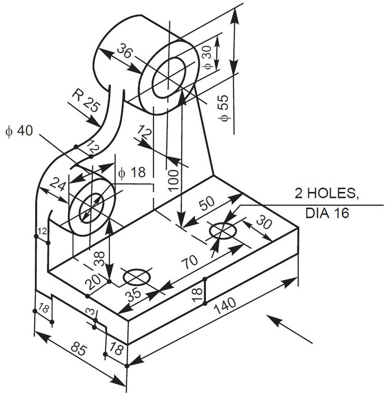
Download How To Read Basic Engineering Drawing Guide Pictures
In that case, the graphic language of the drawing would help manufacturing engineers align their operations according to the drawing drafted by the cad engineer or a draftsman. Web engineering drawing, often referred to as technical or mechanical drawing, is the universal language of engineers and technicians. Correctly creating and reading engineering drawings is an essential ability for engineering technicians..

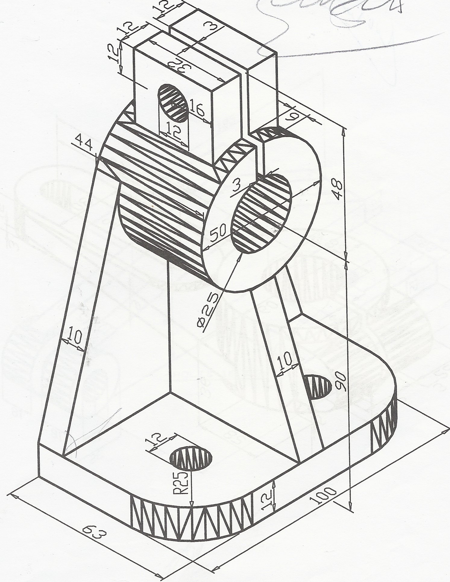
Engineering drawing BASICS OF Engineering drawing
It provides all the necessary information about the object, such as its shape, size, material, and manufacturing process. Technical standards exist to provide glossaries of. It primarily consists of sketching the actual component, for example, a machine, with its exact dimensions, and using entities such as points, lines, arcs,. Hence engineering drawing is a technical drawing conveying information. The purpose.
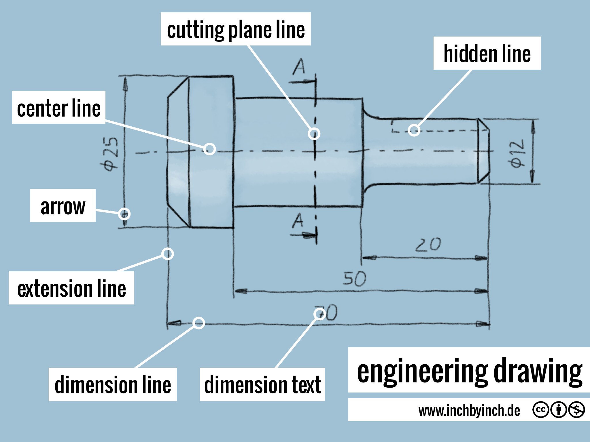
INCH Technical English engineering drawing
Hence engineering drawing is a technical drawing conveying information. Engineering drawings, also known as mechanical drawings, manufacturing blueprints, drawings, etc., are technical drawings that show the shape, structure, dimensions, tolerances, accuracy, and other requirements of a part in the form of a plan. Web we make it ez for you to understand what is engineering drawing ? Engineering drawings use.

Mechanical Engineering Drawing and Design, Everything You Need To Know
Engineering drawings use standardised language and symbols. Web drawing description remarks; Web an animated video attempting to help beginners understand the basics of engineering or technical drawings, introducing them to the various elements they will. Engineering drawings are also known as mechanical drawings, manufacturing blueprints and drawings. It helps to define the requirements of an engineering part.

Engineering Drawing GD&T Basics
In that case, the graphic language of the drawing would help manufacturing engineers align their operations according to the drawing drafted by the cad engineer or a draftsman. Web drawing description remarks; Web although engineers created the engineering drawings in the past by hand, today, they are primarily done in cad software like autodesk fusion 360. Web any engineering drawing.
This Makes Understanding The Drawings Simple With Little To No Personal.
Web an animated video attempting to help beginners understand the basics of engineering or technical drawings, introducing them to the various elements they will. If the isometric drawing can show all details and all dimensions on one drawing, it is ideal. Hence engineering drawing is a technical drawing conveying information. This list includes abbreviations common to the vocabulary of people who work with engineering drawings in the manufacture and inspection of parts and assemblies.
It’s An Essential Skill That Translates Complex Ideas And Theoretical Designs Into Visual Blueprints.
Import) a 3d model, and then we start inserting the views in the drawing and adding dimensions. Drawing in engineering is a way to communicate the details of a product or structure either by hand or with software. A complete understanding of the object should be possible from the drawing. One can pack a great deal of information into an isometric drawing.
Web Any Engineering Drawing Should Show Everything:
Web engineering working drawings basics. Web engineering drawing, most commonly referred to as engineering graphics, is the art of manipulation of designs of a variety of components, especially those related to engineering. The purpose is to convey all the information necessary for manufacturing a product or a part. It primarily consists of sketching the actual component, for example, a machine, with its exact dimensions, and using entities such as points, lines, arcs,.
The Process Of Producing Engineering Drawings Is Often Referred To As Technical Drawing Or Drafting (Draughting).
Engineering graphics is an effective way of communicating technical ideas and it is an essential tool in engineering design where most of the design process is graphically based. Engineering drawings, also known as mechanical drawings, manufacturing blueprints, drawings, etc., are technical drawings that show the shape, structure, dimensions, tolerances, accuracy, and other requirements of a part in the form of a plan. An engineering drawing is a subcategory of technical drawings. Web although engineers created the engineering drawings in the past by hand, today, they are primarily done in cad software like autodesk fusion 360.