What Type Of Drawing Is A Ladder Diagram
What Type Of Drawing Is A Ladder Diagram - Ladder logic is the most common plc programming language, with graphical elements designed to look and respond like electrical device contacts, easier for technicians and electricians to interpret. Web a ladder diagram comprises ‘rails’ that are two parallel lines drawn vertically and represent power supply, and ‘rungs’ that are several lines drawn horizontally with various symbols to connect the ‘rails’ to form an illustration of a control circuit. A ladder diagram, shown in figure 3, is a diagram that explains the logic of the electrical circuit or system using standard nema or iec symbols. A ladder diagram is used to point out relationships between circuit components, not the actual location of the components. In drawing a ladder diagram, certain. Web by peter june 28, 2015. Web ladder diagrams are specialized schematics commonly used to document industrial control logic systems. Web what is a ladder diagram? Each horizontal line in a ladder diagram is identified as a ? They are called “ladder” diagrams because they resemble a ladder, with two vertical rails (supply power) and as many “rungs” (horizontal lines) as there are control circuits to represent.
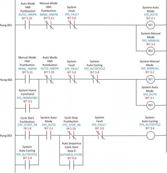
Web a ladder diagram is the symbolic representation of the control logic used for programming of a plc. Web ladder diagram (ld) programming contacts and coils. Web the ladder diagram consists of two vertical lines representing the power rails. , and output devices are placed on the ? Web ladder diagrams show physical placements between the various components in a motor control drawing. How to draw a ladder diagram? Web a ladder diagram comprises ‘rails’ that are two parallel lines drawn vertically and represent power supply, and ‘rungs’ that are several lines drawn horizontally with various symbols to connect the ‘rails’ to form an illustration of a control circuit. Think of ladder logic symbols as the essential pieces of a puzzle in ladder diagrams. They are called “ladder” diagrams because they resemble a ladder, with two vertical rails (supply power) and as many “rungs” (horizontal lines) as there are control circuits to represent. These diagrams documented how connections between devices were made on relay panels;
Each horizontal line in a ladder diagram is identified as a ? They are called “ladder” diagrams because they resemble a ladder, with two vertical rails (supply power) and as many “rungs” (horizontal lines) as there are control circuits to represent. They are called “ladder” diagrams because they resemble a ladder, with two vertical rails (supply power) and as many “rungs” (horizontal lines) as there are control circuits to represent. Web a ladder diagram is the symbolic representation of the control logic used for programming of a plc. What is the most widely used type of drawing for control circuit analysis? How to draw a ladder diagram? Web ladder diagram (ld) programming contacts and coils. Web ladder diagrams (sometimes called ladder logic) are a type of electrical notation and symbology frequently used to illustrate how electromechanical switches and relays are interconnected. Plcs are used in industrial automation applications, such as controlling process equipment, robotics, and other automated machinery. A ladder diagram is used to point out relationships between circuit components, not the actual location of the components.
Ladder Diagram Examples
The two vertical lines (wires) that serve as a boundary for the control system and deliver the. , and output devices are placed on the ? The two vertical lines are called rails and attach to opposite poles of a power supply, usually 120 volts ac. Web ladder diagrams are specialized schematics commonly used to document industrial control logic systems..
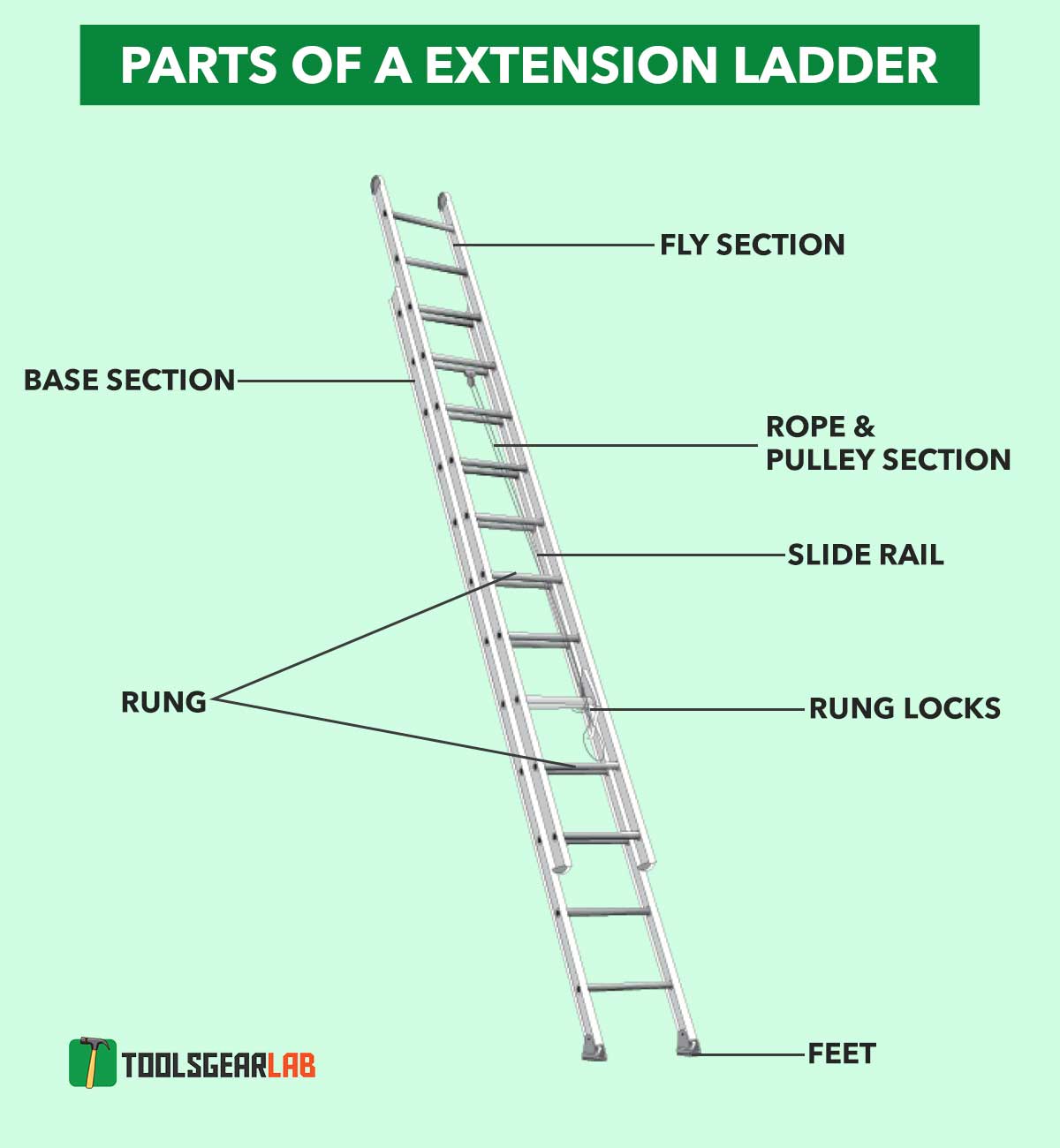
[DIAGRAM] Drawing Ladder Diagram
Plcs are used in industrial automation applications, such as controlling process equipment, robotics, and other automated machinery. Web the ladder diagram consists of two vertical lines representing the power rails. Web there are four basic types of electrical diagrams: In a ladder diagram, input devices are placed on the ? A _____________________ is a type of schematic that represents circuits.
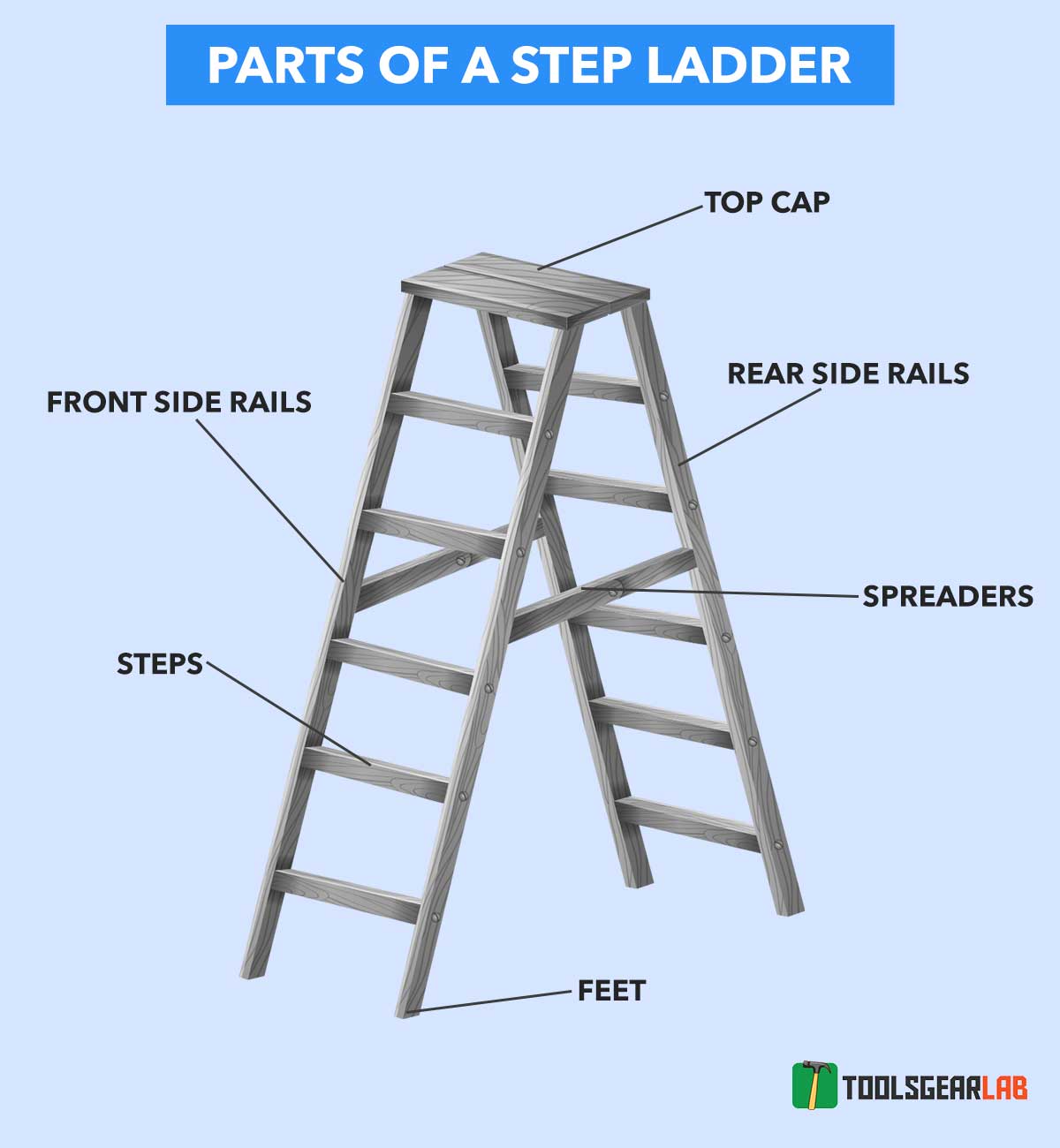
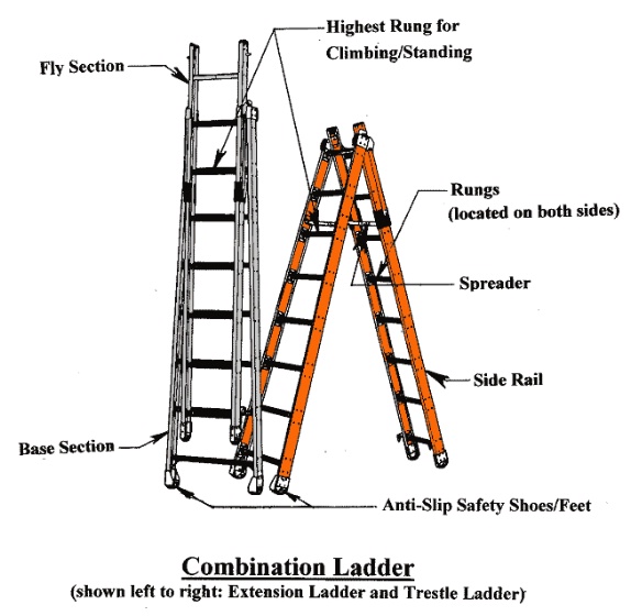
Parts Of A Ladder With Detailed Diagram Picture ToolsGearLab
Web there are four basic types of electrical diagrams: Web a ladder diagram comprises ‘rails’ that are two parallel lines drawn vertically and represent power supply, and ‘rungs’ that are several lines drawn horizontally with various symbols to connect the ‘rails’ to form an illustration of a control circuit. Web a ladder diagram is the symbolic representation of the control.
![[DIAGRAM] Drawing Ladder Diagram](https://www.homestratosphere.com/wp-content/uploads/2018/02/03_Extension-Ladder.jpg)
[DIAGRAM] Drawing Ladder Diagram
Web ladder diagrams show physical placements between the various components in a motor control drawing. These diagrams documented how connections between devices were made on relay panels; Web a ladder diagram is a type of schematic diagram used in industrial automation, describing circuits for logic control. In drawing a ladder diagram, certain. Web ladder diagrams show physical placements between the.
Parts Of A Ladder With Detailed Diagram Picture ToolsGearLab
Web ladder diagrams show physical placements between the various components in a motor control drawing. Determine the initial status of the inputs what type of drawing is a ladder diagram? Web what type of drawing is a ladder diagram? Two vertical control rails and horizontal logic rungs make up the ladder diagrams to form what appears like a ladder. Web.

What Is A Ladder Diagram
Web ladder diagrams (sometimes called ladder logic) are a type of electrical notation and symbology frequently used to illustrate how electromechanical switches and relays are interconnected. Every ladder symbol represents a certain ladder instruction. Web ladder diagram (ld) programming contacts and coils. They are called “ladder” diagrams because they are constructed in a way that resembles a ladder with two.
![[DIAGRAM] Drawing Ladder Diagram](https://www.homestratosphere.com/wp-content/uploads/2018/02/03_Step-Up-Ladder.jpg)
[DIAGRAM] Drawing Ladder Diagram
In drawing a ladder diagram, certain conventions are adopted: It looks just like a ladder, hence the name “ladder diagram”. What is ladder logic & ladder diagram? They are called “ladder” diagrams because they resemble a ladder, with two vertical rails (supply power) and as many “rungs” (horizontal lines) as there are control circuits to represent. Click the card to.
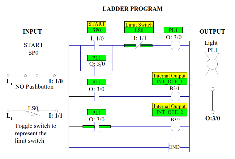
A Simple Ladder Diagram with NO and NC Contacts
Web a ladder diagram comprises ‘rails’ that are two parallel lines drawn vertically and represent power supply, and ‘rungs’ that are several lines drawn horizontally with various symbols to connect the ‘rails’ to form an illustration of a control circuit. Web the ladder diagram consists of two vertical lines representing the power rails. In drawing a ladder diagram, certain conventions.
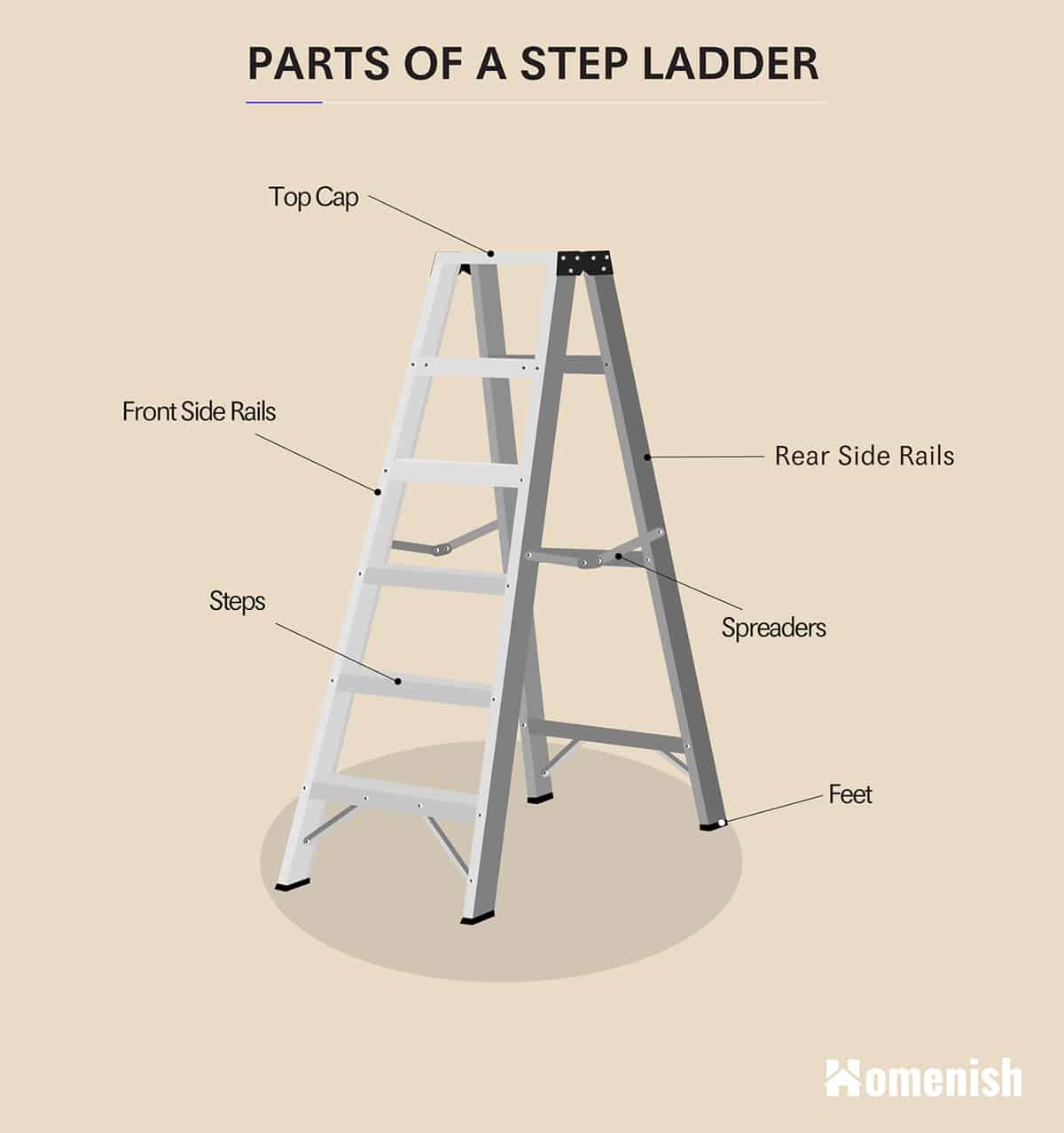
Parts of a Ladder (2 Diagrams For Step Ladder & Extension Ladder
In a ladder diagram, input devices are placed on the ? The two vertical lines (wires) that serve as a boundary for the control system and deliver the. Circuits are connected as horizontal lines, i.e. Web ladder diagrams are specialized schematics commonly used to document industrial control logic systems. The two vertical lines are called rails and attach to opposite.
Ladders 101 American Ladder Institute
Ladder logic is one of the top 5 most popular types of plc programming languages used in manufacturing environments. Web by peter june 28, 2015. Web ladder diagrams (sometimes called ladder logic) are a type of electrical notation and symbology frequently used to illustrate how electromechanical switches and relays are interconnected. Circuits are connected as horizontal lines, i.e., the rungs.
Circuits Are Connected As Horizontal Lines, I.e.
Web a ladder diagram is the symbolic representation of the control logic used for programming of a plc. Ladder logic is the most common plc programming language, with graphical elements designed to look and respond like electrical device contacts, easier for technicians and electricians to interpret. Web ladder diagrams are specialized schematics commonly used to document industrial control logic systems. Web a ladder diagram comprises ‘rails’ that are two parallel lines drawn vertically and represent power supply, and ‘rungs’ that are several lines drawn horizontally with various symbols to connect the ‘rails’ to form an illustration of a control circuit.
They Are Called “Ladder” Diagrams Because They Resemble A Ladder, With Two Vertical Rails (Supply Power) And As Many “Rungs” (Horizontal Lines) As There Are Control Circuits To Represent.
The two vertical lines are called rails and attach to opposite poles of a power supply, usually 120 volts ac. Electronic symbols are widely used when we draw a circuit diagram. Web ladder diagrams show physical placements between the various components in a motor control drawing. A ladder diagram, shown in figure 3, is a diagram that explains the logic of the electrical circuit or system using standard nema or iec symbols.
Web A Ladder Diagram Is A Type Of Schematic Diagram That Is Commonly Used To Document The Wiring Connections And Logic Operations Of A Programmable Logic Controller (Plc).
Web ladder diagrams are specialized schematics commonly used to document industrial control logic systems. Ladder diagrams have horizontal lines of control logic called rungs and vertical lines at the start and end of each rung called rails. Circuits are connected as horizontal lines, i.e., the rungs of the ladder, between these two verticals. A _____________________ is a type of schematic that represents circuits concisely and is.
In Drawing A Ladder Diagram, Certain.
What is the most widely used type of drawing for control circuit analysis? How to draw a ladder diagram? In a ladder diagram, input devices are placed on the ? Web there are four basic types of electrical diagrams: